| « 2021-07-22 | Tinkering | 2021-07-04 » |
Tinkering: 2021-07-07: Table Saw Motor Brake
Part 1: Table Saw Overview.
Part 2: Table Saw Wiring.
Part 3: this article.
Part 4: Table Saw Riving Knife.
Part 5: Table Saw Dust Collection.
This is part 3 of the table saw series. This article is about a modification I made in the circular saw to activate the electronic motor brake when disconnecting power.
Oh, and: do not try this at home. Well, unless you really think you know what you are doing. A circular saw can easily kill you in many ways, especially when operated on. And if it does not kill you, it can injure you. 230 volts can kill or injure you, too. Too much knowledge can also kill or injure you if used wrong. On top of all that, I am quite sure that the following operation will void the saw's warranty. Proceed with utmost caution!
That said, I feel that a disabled motor brake is a big risk, too. Fixing that clearly outweighs warranty issues for me, or the chance of blowing out the circuit breaker.
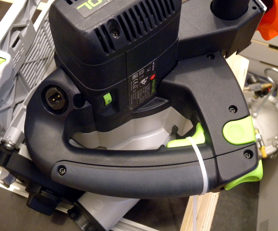 This is my Festool TS 55 REBQ circular saw. It is a very nice saw with a lot of
good safety features. It's a plunge saw, so the saw blade is normally inside an
enclosure so it cannot accidentally be accessed, but needs to be pushed out. It has
a riving knife, which is quite uncommon for hand-held circular saws, but I really
like this. And another feature is the electronic motor brake, which contributes
the 'B' in the saw's name. When releasing the power switch, the saw will enter brake
mode and spin down the blade within around 2s from maximum speed.
This is my Festool TS 55 REBQ circular saw. It is a very nice saw with a lot of
good safety features. It's a plunge saw, so the saw blade is normally inside an
enclosure so it cannot accidentally be accessed, but needs to be pushed out. It has
a riving knife, which is quite uncommon for hand-held circular saws, but I really
like this. And another feature is the electronic motor brake, which contributes
the 'B' in the saw's name. When releasing the power switch, the saw will enter brake
mode and spin down the blade within around 2s from maximum speed.
When this circular saw is used as a table saw, the saw's electric power is not switched on and off with the saw's embedded switch anymore, but instead, that switch is always pushed in (e.g., held in place with a zip tie) and the power is controlled by another switch (or two) in the table. When operating the saw this way, I noticed that this prevents the electronic motor brake from activating when the power is switched off. The blade just normally spins down, and this takes at least 10s. That's not long, you say? Well, after doing some cutting, this operator of the saw has a natural urge to inspect whatever was cut, and this means moving the hands in the direction of the saw blade – but this is not a good idea while that blade is still spinning. I often found myself impatiently waiting for the blade to stop spinning.
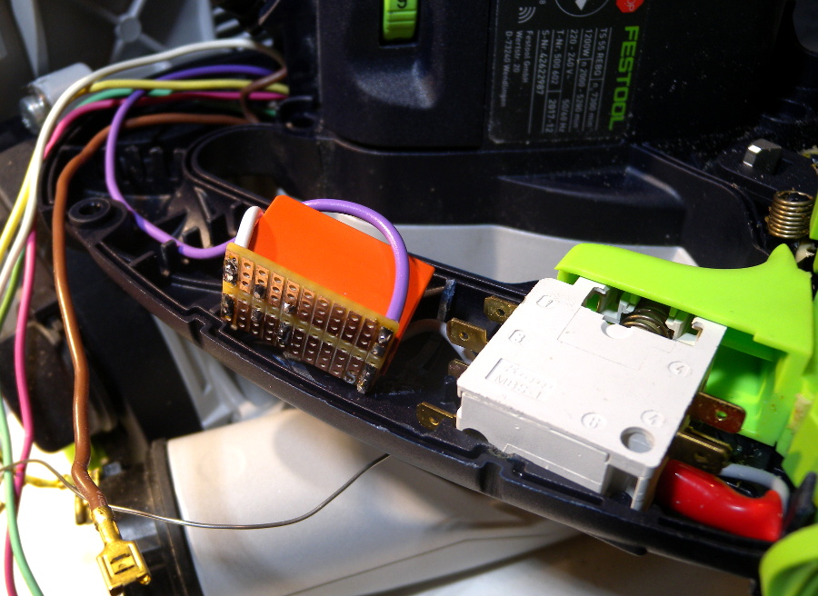
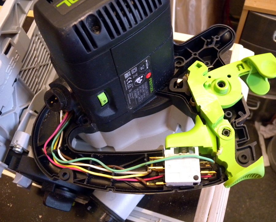 Clearly, something needs to be done to enable the motor brake again. So
let's open the saw and have a look at that power switch. Something must be going
on beyond switching power.
Clearly, something needs to be done to enable the motor brake again. So
let's open the saw and have a look at that power switch. Something must be going
on beyond switching power.
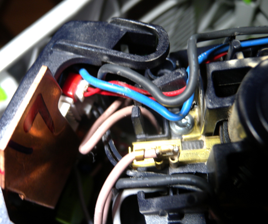
And indeed, five wires connect to the switch, which is clearly more than what is needed for switching power.
The wiring inside the saw looks neat. I will try to make it only minimally worse.
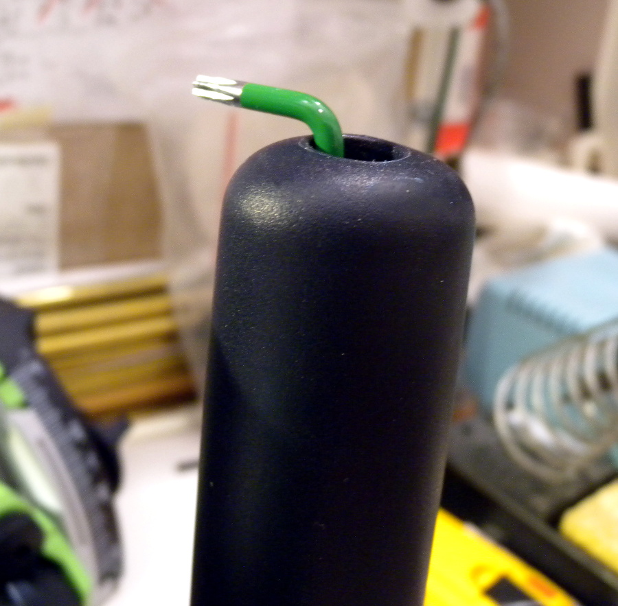 Before we get into that: there is a screw hidden far inside the handle, and I
was lucky: I had bought an L wrench just days before. It was barely long enough
to reach that screw. Any other TORX screw driver or bit
that I had was too short.
Before we get into that: there is a screw hidden far inside the handle, and I
was lucky: I had bought an L wrench just days before. It was barely long enough
to reach that screw. Any other TORX screw driver or bit
that I had was too short.
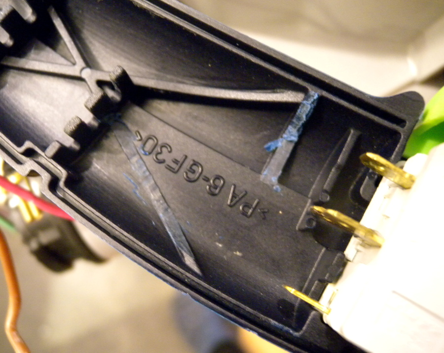
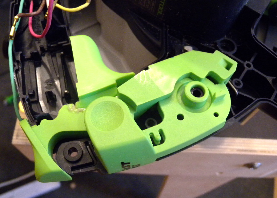 This mechanical part of the handle also needs some care. We will get back to
this later – suffice it to say that I did not re-assemble this correctly
the first time. And it is held down by the top part of the handle that we just
removed, so it really likes to get misaligned.
This mechanical part of the handle also needs some care. We will get back to
this later – suffice it to say that I did not re-assemble this correctly
the first time. And it is held down by the top part of the handle that we just
removed, so it really likes to get misaligned.
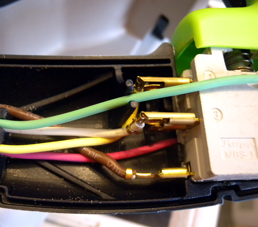 Back to the switch: it is connected on one side to a yellow wire on pin 1,
a white wire on pin 3 and a brown wire on pin 2.
Back to the switch: it is connected on one side to a yellow wire on pin 1,
a white wire on pin 3 and a brown wire on pin 2.
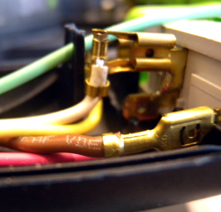 By the way, I really like the 90° cable shoes that are used to optimise
the wiring. I definitely need to get some...
By the way, I really like the 90° cable shoes that are used to optimise
the wiring. I definitely need to get some...
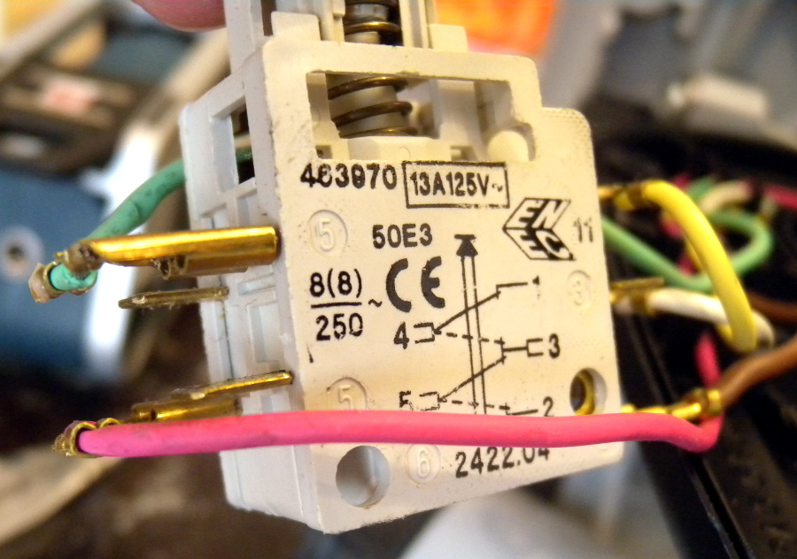 The second side of the switch shows that a green wire is connected to pin 5
and a red wire to pin 4.
The second side of the switch shows that a green wire is connected to pin 5
and a red wire to pin 4.
The back side of the switch also reveals an internal wiring diagram, which can easily be confirmed with a multimeter.
It is hard to say what those wires really do, though.
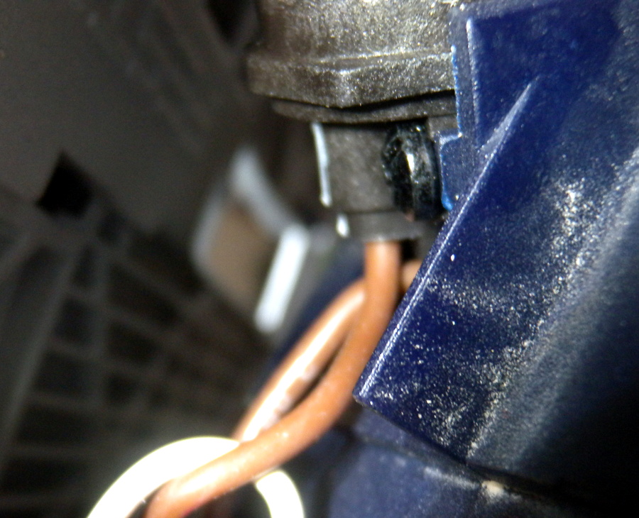 At least the brown wire is easy: it is connected to the power plug. The
power plug has two brown wires coming out of it, and the other one disappears
in the electronics section of the saw.
At least the brown wire is easy: it is connected to the power plug. The
power plug has two brown wires coming out of it, and the other one disappears
in the electronics section of the saw.
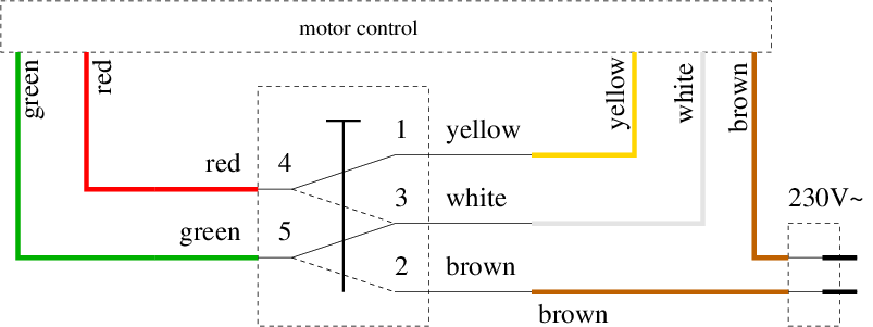 This is a diagram of what we found. Additional to switching power (i.e., connect the
brown wire to the green wire), that
switch connects and disconnects a few control wires (red, yellow, and white) that
all end in the electronics section of the machine. We probably do not need to know
what they do exactly, but just replicate the switching behaviour.
This is a diagram of what we found. Additional to switching power (i.e., connect the
brown wire to the green wire), that
switch connects and disconnects a few control wires (red, yellow, and white) that
all end in the electronics section of the machine. We probably do not need to know
what they do exactly, but just replicate the switching behaviour.
So the idea for making this work also when the power is disconnected externally is to replace that switch by a relay that connects/disconnects the wires in the same way as the switch does now. The switch will then only control the power to the relay, in the same way as an external switch does.
 We do need to dig a little deeper, in particular to find a good
way to access the second power wire that is needed for operating the relay.
So we need to disassemble the saw a little more.
We do need to dig a little deeper, in particular to find a good
way to access the second power wire that is needed for operating the relay.
So we need to disassemble the saw a little more.
The lid on the motor needs to come off, four more screws, and then the electronics section can be pulled out.
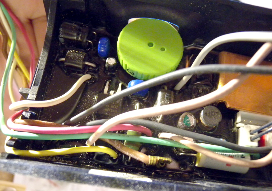 There it is: wires on the left go into the handle, wires on the right go to the
motor. That brown wire on the bottom, with another one of those fancy 90° cable shoes,
that's the second power line. A wire will be soldered to it for the relay
power. It will be nicely shrink-wrapped, of course.
There it is: wires on the left go into the handle, wires on the right go to the
motor. That brown wire on the bottom, with another one of those fancy 90° cable shoes,
that's the second power line. A wire will be soldered to it for the relay
power. It will be nicely shrink-wrapped, of course.
As can also be seen here, there is no way of knowing what the other wires do, because they disappear into black resin that floods the whole PCB together with the casing. If this board is accidentally blown up by misconnecting some wires, I really hope this whole thing is available as a spare part.
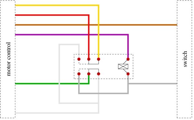
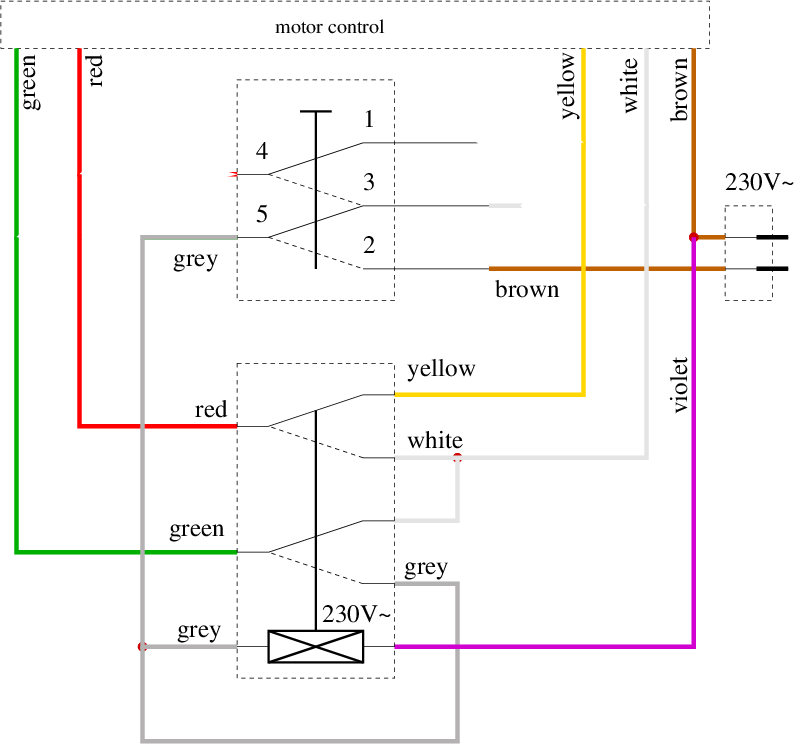 This is a diagram of what we will do: we will use a relay to take the
function of the switch. That new
violet wire is the second power line to operate the relay coil. The original power
switch will control the first power line (grey wires), which
will switch the relay and provide power to the saw. And this simple switching can then
also be done with an external switch to the same effect.
This is a diagram of what we will do: we will use a relay to take the
function of the switch. That new
violet wire is the second power line to operate the relay coil. The original power
switch will control the first power line (grey wires), which
will switch the relay and provide power to the saw. And this simple switching can then
also be done with an external switch to the same effect.
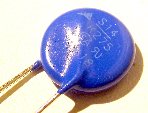 Not depicted in the schematics, I added this varistor later in parallel
to the relay's coil because I remembered that it is a good idea to do so.
It is a good idea – the coil, disconnected from 230V may cause spikes of
several thousand volts that will somehow discarge, probably as a spark
across the switching contacts. The varistor has very high resistance at
230V, so it won't add much to energy consumption in the normal case, but
it has very low resistance at the much higher voltage that builds up after
switching off the relay, and it will thus consume that energy. The nominal
threshold AC voltage of the varistor is the max. expected normal case voltage,
which is around 250V here, plus like 10% margin.
Not depicted in the schematics, I added this varistor later in parallel
to the relay's coil because I remembered that it is a good idea to do so.
It is a good idea – the coil, disconnected from 230V may cause spikes of
several thousand volts that will somehow discarge, probably as a spark
across the switching contacts. The varistor has very high resistance at
230V, so it won't add much to energy consumption in the normal case, but
it has very low resistance at the much higher voltage that builds up after
switching off the relay, and it will thus consume that energy. The nominal
threshold AC voltage of the varistor is the max. expected normal case voltage,
which is around 250V here, plus like 10% margin.
 To reduce the chance of soldering mistakes when working on the relay, I made
another diagram that shows how the relay physically needs to be connected.
This is a bottom view of the relay.
To reduce the chance of soldering mistakes when working on the relay, I made
another diagram that shows how the relay physically needs to be connected.
This is a bottom view of the relay.
 First, we need a little more space in the handle. Top and bottom parts were treated
with a chisel. With its help, the handle has plenty enough room for the relay plus
a little PCB for cable management.
First, we need a little more space in the handle. Top and bottom parts were treated
with a chisel. With its help, the handle has plenty enough room for the relay plus
a little PCB for cable management.
 The PCB I use with the relay is a simple strip board where I cut out sections
of copper. Later I also removed every second strip of copper to maintain the
contact distance.
The PCB I use with the relay is a simple strip board where I cut out sections
of copper. Later I also removed every second strip of copper to maintain the
contact distance.
The relay is rated for 230V~/8A, which is enough for the saw. It is quite small, so I think we might be out of spec for contact disconnection – the original switch looks massive, and I am sure it has a large gap between open contacts, and it may ensure clean disconnection before reconnection. I am not so sure about these features in the relay. But we do not know the specs, so we do not know what is needed. So let's not worry, because this operation adds a safety feature back to the saw.
BTW, the original switch is made by Kopp, who usually make consumer light switches and power connectors. I did not find any specs about this switch, but the Festool part number is printed on it, so this is a part that end users will not buy from Kopp directly. Hence no specs.
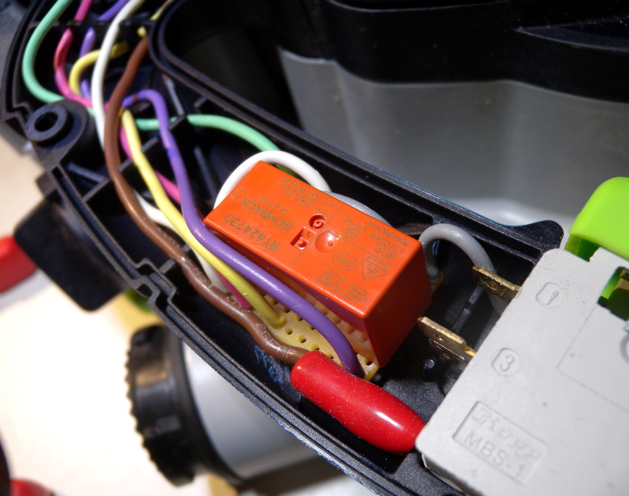 There the relay is, all connected. It fits nicely into the handle, and the
top of the handle also still fits. That's it, we're done! Close the lid,
switch it on!
There the relay is, all connected. It fits nicely into the handle, and the
top of the handle also still fits. That's it, we're done! Close the lid,
switch it on!
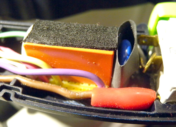 Before closing the lid, I added the varistor, some shrink wrap around
it, and put some self-sticking synthetic rubber tape on top to gently
hold it in place.
Before closing the lid, I added the varistor, some shrink wrap around
it, and put some self-sticking synthetic rubber tape on top to gently
hold it in place.
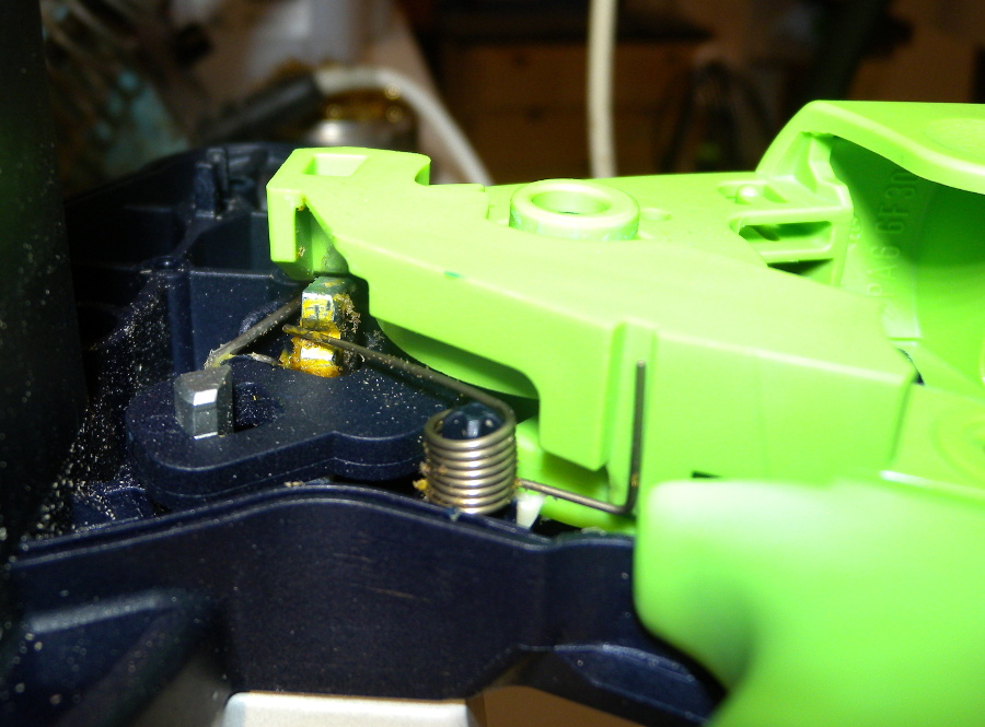 Small problem encountered when putting the lid back on: this spring in the
mechanical part of the switch needed some care. It was
in the wrong place when I first reassembled the handle. The switch was somehow
jammed and would not operate mechanically, so I had to re-open the handle and
correct the fitting of this spring.
Small problem encountered when putting the lid back on: this spring in the
mechanical part of the switch needed some care. It was
in the wrong place when I first reassembled the handle. The switch was somehow
jammed and would not operate mechanically, so I had to re-open the handle and
correct the fitting of this spring.
 It was not easy to really test the correct wiring without the danger of blowing up
the electronics board or blowing out the circuit breaker, because how can I test the
motor brake without motor power? And motor power means, well, full 230V~ power.
Also, the function of the wires is unknown,
so nothing can really be tested there either. I decided to carefully recheck all the
connections, and then just switch it on. And off, of course! And it did not
blow out the circuit breaker, the motor worked, and the brake also worked!
It was not easy to really test the correct wiring without the danger of blowing up
the electronics board or blowing out the circuit breaker, because how can I test the
motor brake without motor power? And motor power means, well, full 230V~ power.
Also, the function of the wires is unknown,
so nothing can really be tested there either. I decided to carefully recheck all the
connections, and then just switch it on. And off, of course! And it did not
blow out the circuit breaker, the motor worked, and the brake also worked!
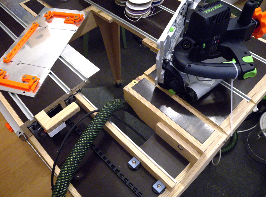
So the saw can now be put back into the table, and I have my motor brake back!
There is still work to be done on this machine: the next episode shows how I built a new riving knife.