| « 2021-07-04 | Tinkering | 2020-12-06 » |
Tinkering: 2021-06-14: Table Saw Overview
Part 1: this article.
Part 2: Table Saw Wiring.
Part 3: Table Saw Motor Brake.
Part 4: Table Saw Riving Knife.
Part 5: Table Saw Dust Collection.
For my workshop, I needed a table. To minimize usage of space, I had the idea for a while to build a table with a changeable aluminium insert to make it a table saw or a router table. And for the table saw, I wanted to improve in major ways on the guide rails that I use now, so I wanted a sled where I can clamp down stuff to be cut. So that's the project presented here.
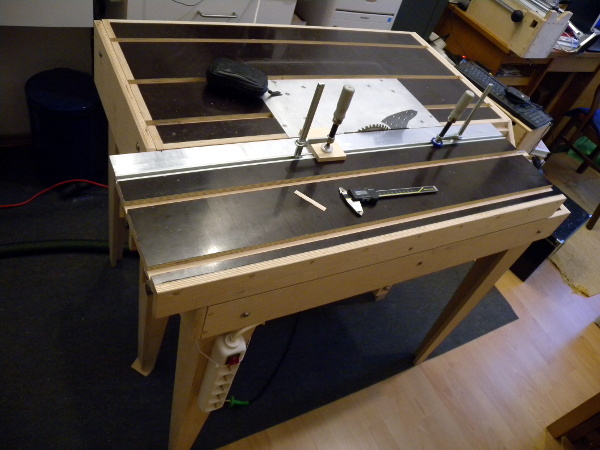 This is it, finished after a while of tinkering. The table has the promised sled,
which uses rods and cheap bearing blocks – it is basically the usual
construction upside down: bearing blocks on the bottom. I did not use 'proper'
bearing blocks, because the construction is from plywood, and I feared that I cannot
match the required precision. By reversing the normal construction, the bearing
blocks are fixed and close to the saw, holding the sled tight exactly where
the action happens.
This is it, finished after a while of tinkering. The table has the promised sled,
which uses rods and cheap bearing blocks – it is basically the usual
construction upside down: bearing blocks on the bottom. I did not use 'proper'
bearing blocks, because the construction is from plywood, and I feared that I cannot
match the required precision. By reversing the normal construction, the bearing
blocks are fixed and close to the saw, holding the sled tight exactly where
the action happens.
Pieces of material can be clamped down on the sled. The t-slots for this are not all glued in yet, but the image should give the general idea: the slots are already cut.
There will also be a 90° front part on the sled to implement a cross cut sled. Further, I will add a digital read-out, which may be overkill, but why not?
The table is built from plywood. The brown top is a phenolic finish on plywood, which is also available off the shelf like that. The edge of the sled is an aluminium L-profile. There is more aluminium in the sled for stabilisation. I cut all this with the very saw that is now part of the table. Cutting the aluminium was not fun, and I had to cut it length-wise twice for the 45° edges. It was probably the wrong alloy – very sticky, it felt almost like firm tar, and not really machinable, leaving a horrific burr. Using some isopropyl alcohol improved it a bit.
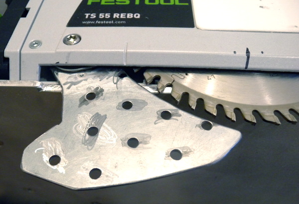
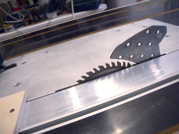 This is the saw blade peeking out of the table. What looks like a home-made riving
knife is actually a home-made riving knife. You could buy this from Festool – they
have a conversion set for under-table mounting which contains it. But I found
Festool's price of ~50 EUR for a small piece of 2mm sheet metal unacceptable.
OK, it is bent. But, no, my stubbornness does
not allow for this, even if it takes me hours to figure out the exact shape, and to
find ways to make this at home (I cannot bend 2mm steel sheet the way the original
is bent.) Other parts of the conversion set I did buy from
Festool, because it was just easier this way and the price was a little
more agreeable.
This is the saw blade peeking out of the table. What looks like a home-made riving
knife is actually a home-made riving knife. You could buy this from Festool – they
have a conversion set for under-table mounting which contains it. But I found
Festool's price of ~50 EUR for a small piece of 2mm sheet metal unacceptable.
OK, it is bent. But, no, my stubbornness does
not allow for this, even if it takes me hours to figure out the exact shape, and to
find ways to make this at home (I cannot bend 2mm steel sheet the way the original
is bent.) Other parts of the conversion set I did buy from
Festool, because it was just easier this way and the price was a little
more agreeable.
The table insert is from 5mm aluminium, which is exactly the thickness of the normal Festool guide rails, so that the table saw tilt axis is exactly at the surface of the table. This means I need only a narrow opening for the blade. The saw uses trunnions internally to implement this, which sets it apart from cheap circular saws that are not made for guide rails.
First test cuts show I can cut off 1mm from a piece of plywood without problems, and with about 0,1mm of repeatability. This is great!
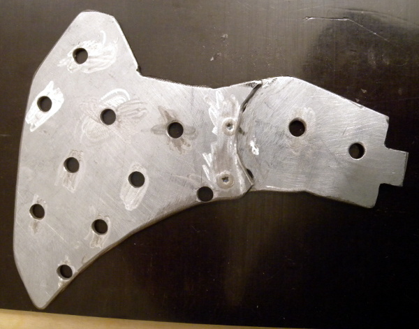 This is the riving knife in detail, with its lower part that is attached to the
short riving knife of the saw, and its upper part that is much larger for this
purpose so that additional dust extraction can be mounted. One of the lower
part's holes is tapped to M6 to mate with the mounting bolt.
This is the riving knife in detail, with its lower part that is attached to the
short riving knife of the saw, and its upper part that is much larger for this
purpose so that additional dust extraction can be mounted. One of the lower
part's holes is tapped to M6 to mate with the mounting bolt.
Unfortunately, this version is not completely in line with the blade – it works, but not perfectly. Also, I cut the knife too short so I cannot attach a dust collection at full 50mm cutting height. So I think I need to remake it. No, despite the hassle, I am not buying this as a spare part.
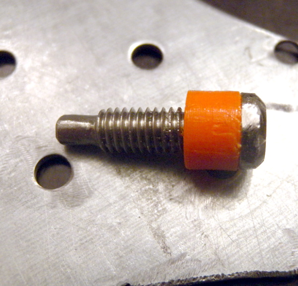 This is the special mounting bolt for the riving knife that I made. It is an M6
thread, but it has a tip that fits into a socket in the saw – it is exactly the
pivot point of the saw's plunge mechanism so that the riving knife moves exactly
together with the blade. I eye-balled the socket size to be something like 4mm,
and then filed down the bolt by hand (I have no lathe).
This is the special mounting bolt for the riving knife that I made. It is an M6
thread, but it has a tip that fits into a socket in the saw – it is exactly the
pivot point of the saw's plunge mechanism so that the riving knife moves exactly
together with the blade. I eye-balled the socket size to be something like 4mm,
and then filed down the bolt by hand (I have no lathe).
The second special part of the bolt is a long collar that tightens against the short riving knife of the saw. It would be possible to just use a shorter bolt, but getting the bolt in and out would become awkward. I just 3D printed the collar so that the bolt is flush with the saw's casing. The original bolt has a large flange and thus does not screw into the saw completely, but sticks out a bit. I prefer it to be flush so I am sure that I can tilt the saw without hitting the sled.
If you are wondering: yes, I was too stubborn to buy this bolt as a spare part.
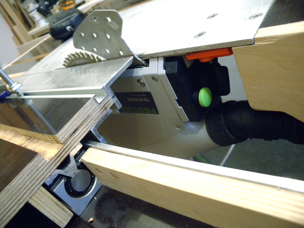 When the sled is pulled all the way to the front, the back part of the saw
can be accessed. This is where the dust extraction attaches, and there is
also one knob needed for the tilting mechanism. Further, the riving knife
mounting bolt is accessible from here. Everything that is necessary can
be accessed. Not conveniently by any means, but it can be accessed.
When the sled is pulled all the way to the front, the back part of the saw
can be accessed. This is where the dust extraction attaches, and there is
also one knob needed for the tilting mechanism. Further, the riving knife
mounting bolt is accessible from here. Everything that is necessary can
be accessed. Not conveniently by any means, but it can be accessed.
This also shows how much space is left under the sled to allow the saw to completely tilt to 45°. It was a major design problem to get this done. The sled is reenforced with aluminium profiles to allow it to have an overhang, and the one profile facing the blade needs to have a 45° relief cut at the edge to allow the blade to tilt. The tilting axis is on the right side of the blade (from this viewing angle) at the top of the table, which means that the blade will move towards the sled and up. The gap between the sled and the blade is still only maximally 2mm. This is very OK, so I could probably push it even a little more...
The bearing blocks and rail rods of the sled can also be seen in this picture.
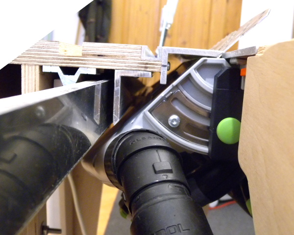 This picture shows the saw tilted to the full 45° angle. I don't think
I can do the complete full 47° the saw could do. The distance between the
saw and the sled is only ~2mm horizontally and practically 0mm vertically
close to the blade. But the sled does clear the saw, so the saw is usable
this way.
This picture shows the saw tilted to the full 45° angle. I don't think
I can do the complete full 47° the saw could do. The distance between the
saw and the sled is only ~2mm horizontally and practically 0mm vertically
close to the blade. But the sled does clear the saw, so the saw is usable
this way.
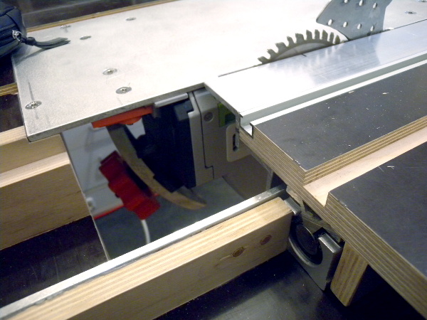 The front side is also accessible in the same way as the back: just move
the sled to the other end. The front is needed to adjust the blade height.
Again, it is not convenient, but it works. This has the special complication
that the saw is spring loaded to counter-act its weight, but that is the
wrong direction for under table mounting: it pushes down. Furthermore, the
weight of the saw also pulls it down. Loosening the screw for changing
the blade depth is prone to making the saw fall down and ram into its
0mm position stop. Well, not ideal. But at least height adjustment it
accessible.
The front side is also accessible in the same way as the back: just move
the sled to the other end. The front is needed to adjust the blade height.
Again, it is not convenient, but it works. This has the special complication
that the saw is spring loaded to counter-act its weight, but that is the
wrong direction for under table mounting: it pushes down. Furthermore, the
weight of the saw also pulls it down. Loosening the screw for changing
the blade depth is prone to making the saw fall down and ram into its
0mm position stop. Well, not ideal. But at least height adjustment it
accessible.
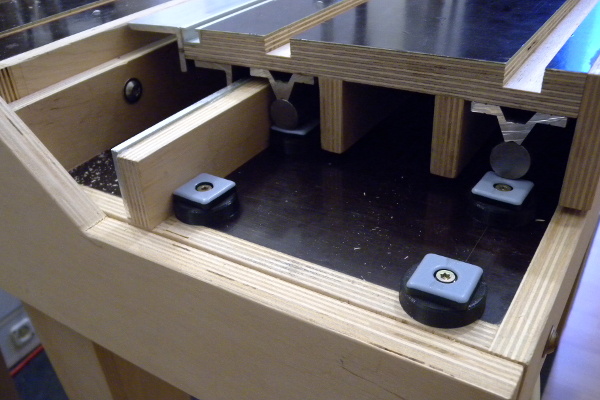 The sled has quite a bad overhang when extended to one side: it is held by
the bearings on only 20cm length, but the sled is 1m long, so the overhang
is 80cm. It is also heavy, and material will be mounted on it. All
this is made worse by the 1:4 lever from the overhang. The bearings
can probably take a lot, but maybe not this. And if you accidentally
lean on the sled, they may break.
The sled has quite a bad overhang when extended to one side: it is held by
the bearings on only 20cm length, but the sled is 1m long, so the overhang
is 80cm. It is also heavy, and material will be mounted on it. All
this is made worse by the 1:4 lever from the overhang. The bearings
can probably take a lot, but maybe not this. And if you accidentally
lean on the sled, they may break.
To counter this problem, I put some teflon gliders on the table to support the rail rods. This makes pushing the table a bit harder, but it is still smooth thanks to the teflon. The overhang is very much limited this way. We'll see how this solution works out.
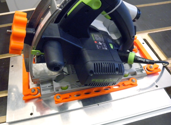 This is the saw upside up attached to the mounting plate that goes into the
table. The neon orange parts are 3D prints. For this build, I bought
some parts of the conversion kit, e.g., the modified height adjustment. I
could have 3D printed this, but it is much more rigid in metal and it would
have taken me really long to figure out the exact shape. The knob that came
with it stuck out too much so the saw would not fit into the table, so I
printed a new and flat one.
This is the saw upside up attached to the mounting plate that goes into the
table. The neon orange parts are 3D prints. For this build, I bought
some parts of the conversion kit, e.g., the modified height adjustment. I
could have 3D printed this, but it is much more rigid in metal and it would
have taken me really long to figure out the exact shape. The knob that came
with it stuck out too much so the saw would not fit into the table, so I
printed a new and flat one.
There are three principle parts for actually mounting the saw to the aluminium: positioning blocks, in the back and on the sides, and clamping brackets that can be pulled in and out for easy mounting.
Also note the ultimate professional solution for pressing the power button: a zip tie! Yes, I could have 3D printed this and I might do that later, but this works fine for now.
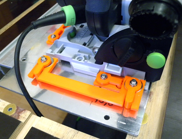 This is one of the sides with the clamping bracket and one of the
positioning blocks. The positioning blocks can be moved by ~1mm to
adjust exactly where the saw is, to make it exactly the right
distance from the sled's edge, and to make the blade parallel to the
sled's movement.
This is one of the sides with the clamping bracket and one of the
positioning blocks. The positioning blocks can be moved by ~1mm to
adjust exactly where the saw is, to make it exactly the right
distance from the sled's edge, and to make the blade parallel to the
sled's movement.
The clamping brackets are reenforced with a large steel washer so that the saw is not held in place purely by 3D printed plastic. I feel better this way.
All the nuts in the machine mounting assembly are self-securing nylon insert nuts so vibrations will not wiggle them loose.
All the screws are tightened from above, which is suboptimal for the clamping brackets, but I found no easy way to have a nut embedded in the aluminium, as there is no space for a regular nut in 5mm of aluminium. I also did not want a thread in soft aluminium. Maybe something could have been brazed, but I don't usually braze.
 This is another shot of the riving knife. It is two pieces instead of
one that is bent. The lower piece that is not visible here, because it
is behind the upper piece, mounts to the existing small riving knife of
the saw. The visible larger part is riveted to the smaller part. The
rivets are solid pieces of steel hammered into the rivet holes (which
have a chamfer, so it holds tight), and then sanded down. There is
no space for anything sticking out.
This is another shot of the riving knife. It is two pieces instead of
one that is bent. The lower piece that is not visible here, because it
is behind the upper piece, mounts to the existing small riving knife of
the saw. The visible larger part is riveted to the smaller part. The
rivets are solid pieces of steel hammered into the rivet holes (which
have a chamfer, so it holds tight), and then sanded down. There is
no space for anything sticking out.
The saw sounds grown-up in the table. Quite seriously aggressive in a very confident way. It seems that the table enhances the lower frequencies of the saw's noise. Nice. It is clear that you should not mess with it. And it is surprisingly not too loud.
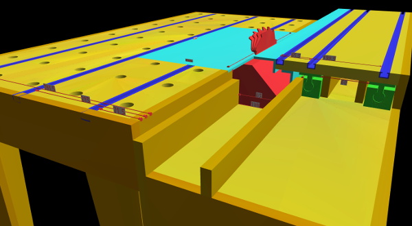 Of course I made a 3D model of the table before starting. There were
quite a few surprises of things getting in the way: the dust extraction
hose, of course the tilting action of the saw, but also the motor and
several other things. Despite all the cut-offs, the table needs to be
rigid, so the task was to balance making space vs. enforcing the table.
Of course I made a 3D model of the table before starting. There were
quite a few surprises of things getting in the way: the dust extraction
hose, of course the tilting action of the saw, but also the motor and
several other things. Despite all the cut-offs, the table needs to be
rigid, so the task was to balance making space vs. enforcing the table.
So that's my new working table, convertible into a table saw. This is not over, more on this sooner or later.
Part 2: there is an article about the wiring of the table.