| « 2020-12-06 | Tinkering | 2020-10-15 » |
Tinkering: 2020-11-18: An Alarm Clock
Part 1: this article.
Part 2: updated version, padouk wood.
Part 3: last incarnation, amaranth wood.
Part 4: alarm clock repair.
A while back, I built the 'About O'Clock' wall clock. Because it came out quite nice, I wanted an alarm clock with this design. After learning how to do SMD PCBs with Kicad and manufacturing them in China, I was able to achieve the level of integration necessary for fitting everything into a small enclosure. The first prototype is finished and functional, and here are the first pictures. I plan on building two more alarm clocks like this, with slightly improved specs based on what I learned here.
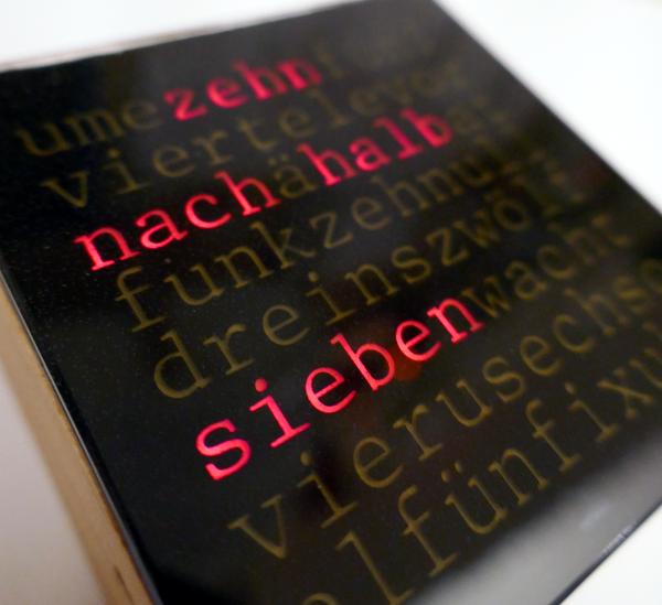
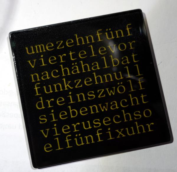
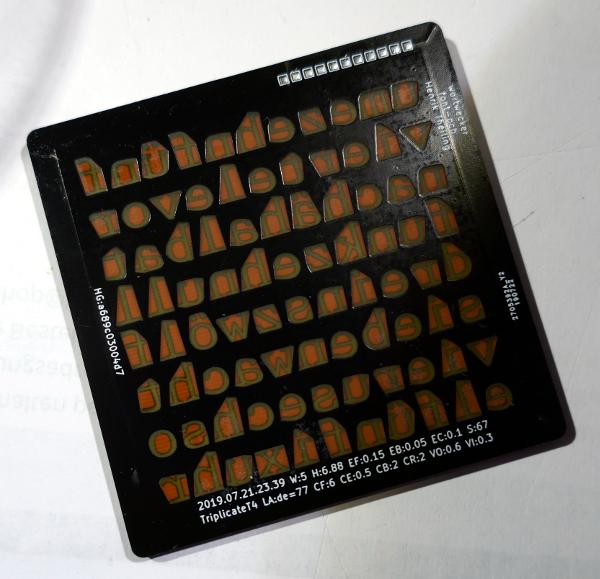
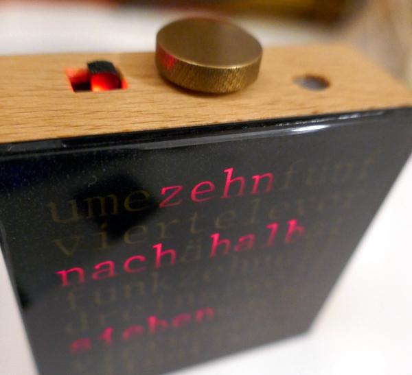 This is the finished alarm clock. The clock face uses a nice font
that took me a long time to find:
Triplicate by Matthew Butterick.
The font is really good for this because it is monospaced and
beautiful. I can use natural letter spacing for the grid. This is
so much nicer than using Helvetica all upper case
letters with huge empty spaces between the letters, like many word
clocks out there do.
This is the finished alarm clock. The clock face uses a nice font
that took me a long time to find:
Triplicate by Matthew Butterick.
The font is really good for this because it is monospaced and
beautiful. I can use natural letter spacing for the grid. This is
so much nicer than using Helvetica all upper case
letters with huge empty spaces between the letters, like many word
clocks out there do.
The size of the alarm clock is 67mm x 67mm x 26mm (excluding the knob and alarm switch), so it is pretty small, but not the smallest alarm clock in the world. It weighs 146g.
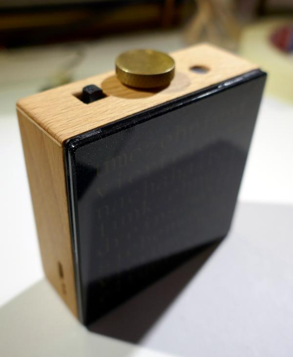 The crystal is glass. Not acrylic, but real glass.
The enclosure is wood, because my wife had joked that it would be nice. She is right, so there we are.
 The clock uses 176 LEDs for the display in two colours: red and yellow, i.e.,
two LEDs for each of the 88 letters. Red is used for night display (6pm..6am)
and yellow is used during the day (6am..6pm).
The clock uses 176 LEDs for the display in two colours: red and yellow, i.e.,
two LEDs for each of the 88 letters. Red is used for night display (6pm..6am)
and yellow is used during the day (6am..6pm).
The two colour display distinguishes this alarm clock from my wall clock. For setting the alarm, I wanted to be able to use a full night and day 24h range instead of just 12h.
My wife and I had long sessions of comparing the colours of LEDs to select the most beautiful ones. Unfortunately, the camera does not really do a good job at capturing the colours.
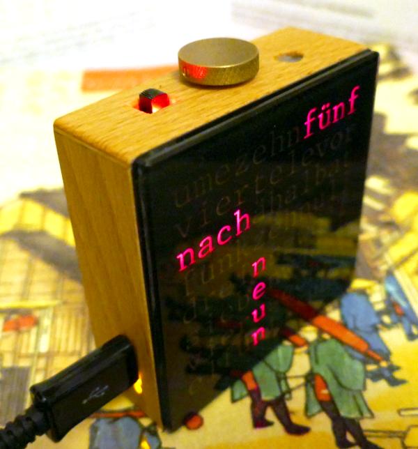
 The alarm time display is indicated by using the preposition 'um',
meaning 'at'.
The alarm time display is indicated by using the preposition 'um',
meaning 'at'.
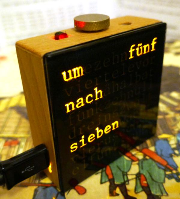
 For the normal time display, the clock does not use
a preposition.
For the normal time display, the clock does not use
a preposition.
 This is the back side of the alarm clock with one hole for the buzzer
and another hole for the coffee machine connector. Yes, that small 2.5mm
audio jack can switch on a coffee machine. OK, that coffee machine is
not built yet, but it's on my list of projects...
This is the back side of the alarm clock with one hole for the buzzer
and another hole for the coffee machine connector. Yes, that small 2.5mm
audio jack can switch on a coffee machine. OK, that coffee machine is
not built yet, but it's on my list of projects...
The coffee machine connector is an open drain that can switch quite a bit of power, limited mainly by the small wires that I use inside the clock. The MOSFET can do 20V at 3A or so (it's an IRLML2502), but I would not feel very comfortable with a current above 250mA.
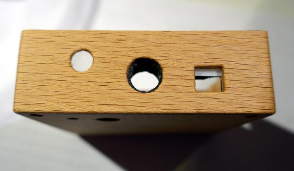
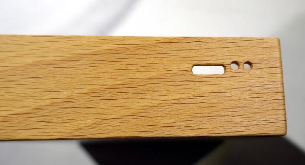 The clock uses a lithium polymer battery (3,7V) with 1000mAh, and it
has a USB connector (currently micro USB-B) for charging. That's what
this oblong hole is for. The two holes next to it are for status LEDs
of the charger circuit ('charging' and 'error').
The clock uses a lithium polymer battery (3,7V) with 1000mAh, and it
has a USB connector (currently micro USB-B) for charging. That's what
this oblong hole is for. The two holes next to it are for status LEDs
of the charger circuit ('charging' and 'error').
I use an LTC4053 and LTC4410 combo for doing the USB stuff – the main micro-controller does not care at all about this. It does have a USB power sense, though, so that the display will stay on when there's wall power.
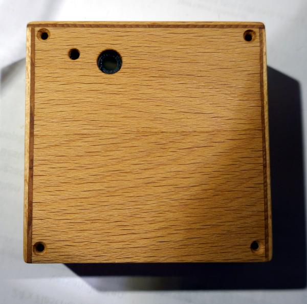 This is the back side of the wooden enclosure where the plies are
visible: I cut two plies of around 1mm from a piece of beech hardwood
and glued them back together with the grain direction at a right angle
to stabilise it. The difference
in grain direction causes this nice colour change, framing the enclosure.
This is the back side of the wooden enclosure where the plies are
visible: I cut two plies of around 1mm from a piece of beech hardwood
and glued them back together with the grain direction at a right angle
to stabilise it. The difference
in grain direction causes this nice colour change, framing the enclosure.
I suppose one would usually use three plies or any other odd number for stabilisation, but the wood is glued to an inner 3D printed plastic skeleton that also acts as another layer of stabilisation, so 2-ply should be fine.
The wood is finished with hardwax oil.
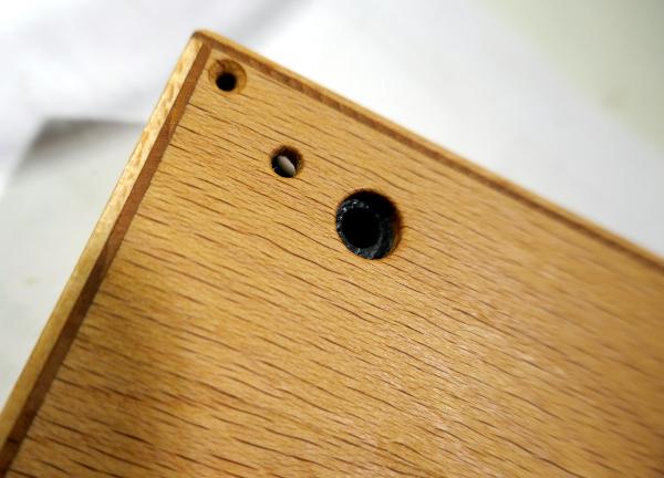 The buzzer and coffee machine holes again, and the countersunk screw
hole for bolting the enclosure to the electronics inside.
The buzzer and coffee machine holes again, and the countersunk screw
hole for bolting the enclosure to the electronics inside.
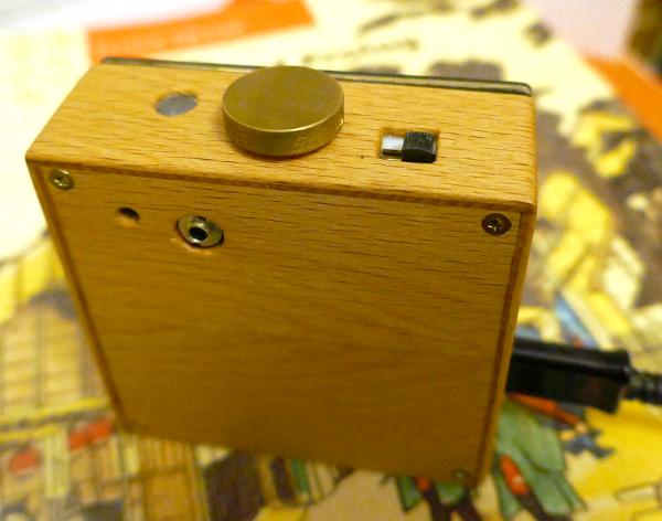
 The top of the clock has holes for the ambient light sensor, for the
main control knob, and for the alarm on/off switch, where there's also
another red LED for indicating whether the alarm is switched on.
The top of the clock has holes for the ambient light sensor, for the
main control knob, and for the alarm on/off switch, where there's also
another red LED for indicating whether the alarm is switched on.
 The clock face and crystal.
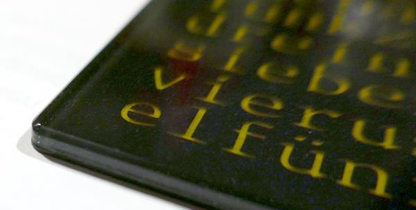 The face and the crystal are glued together with epoxy, and it came
out OK. This corner looks perfect, but I need a few more tries
to get it really right. This is a prototype, and I am still
experimenting. There are tiny bubbles in the epoxy (I will purchase a
pressure pot to deal with that) and the glue layer is unevenly thick –
a dumb mistake. The mistakes are not visible in these selected
pictures.
The face and the crystal are glued together with epoxy, and it came
out OK. This corner looks perfect, but I need a few more tries
to get it really right. This is a prototype, and I am still
experimenting. There are tiny bubbles in the epoxy (I will purchase a
pressure pot to deal with that) and the glue layer is unevenly thick –
a dumb mistake. The mistakes are not visible in these selected
pictures.
The glass was cut from a 2mm sheet of glass as precisely as possible, with a goal of 0,2mm larger dimensions, and it took only two attempts to get there. Then I wet sanded it by hand with water-proof sand paper with grit sizes 120, 220, 400, 800, 1500, and 3000. The front side of the glass has a small bevel. The corners are rounded just like the clock face and the enclosure. The finished edges and corners came out really nice.
 This is the back side of the clock face, showing that it is just
another PCB that I made with Kicad
and Perl.
I converted the
Triplicate font files to an SVG font with fontforge,
so that I could
easily read the outlines with Perl. Then I processed the outlines
with OpenSCAD to make them a bit larger.
From this data, back in Perl,
I computed the convex hulls for the back side, and generated the Kicad
copper layer and solder mask polygons.
This is the back side of the clock face, showing that it is just
another PCB that I made with Kicad
and Perl.
I converted the
Triplicate font files to an SVG font with fontforge,
so that I could
easily read the outlines with Perl. Then I processed the outlines
with OpenSCAD to make them a bit larger.
From this data, back in Perl,
I computed the convex hulls for the back side, and generated the Kicad
copper layer and solder mask polygons.
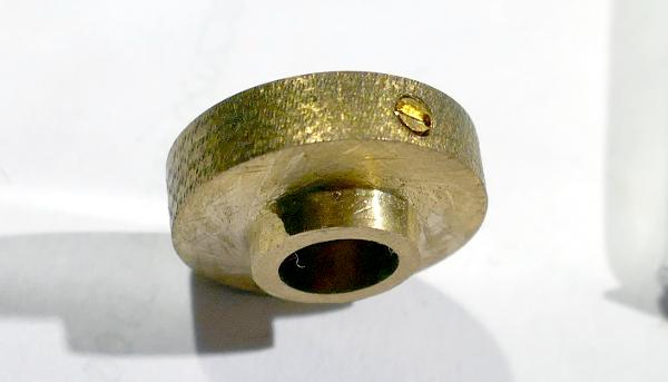 This is the main knob that I made from brass. I tried to find a nice knob,
but there just was none that I liked. I then got myself a brass rod
from eBay and used very crude techniques involving a drill press, hand saws
and files, and battery powered drills to turn the knob. I have no lathe, so
this was the only way for me. The knurling was done with a file and some
violence. The knob has an M2 thread for a grub screw – I also cut the
grub screw myself from a slotted, countersunk M2 brass screw because there was
nothing with exactly the right length that I could find.
This is the main knob that I made from brass. I tried to find a nice knob,
but there just was none that I liked. I then got myself a brass rod
from eBay and used very crude techniques involving a drill press, hand saws
and files, and battery powered drills to turn the knob. I have no lathe, so
this was the only way for me. The knurling was done with a file and some
violence. The knob has an M2 thread for a grub screw – I also cut the
grub screw myself from a slotted, countersunk M2 brass screw because there was
nothing with exactly the right length that I could find.
Oh and I do not want this shiny. It was shiny, but the knurl will quickly look used anyway, and I like the patina.
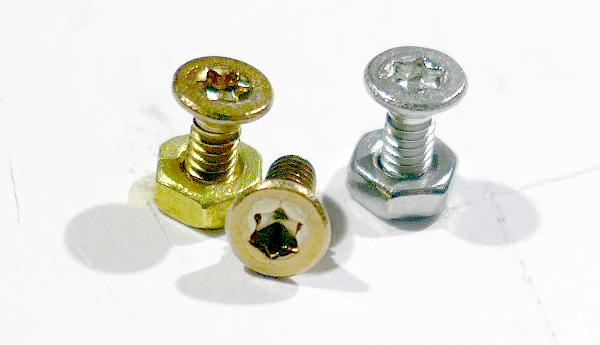 These are the screws for bolting the enclosure to the inner parts of
the clock. I tried to find M2 brass screws with torx drive (DIN965),
because torx screws just look more elegant than slotted or philips
screws. But I couldn't find any. Stainless steel was no problem,
though. So I got steel screws and heat treated them with a blowtorch
(well, with a Searzall, really)
to get a brass like colour. It worked
perfectly: the screw on the left is the same steel screw as on the
right, only heat treated. The nut it is screwed to is brass, which is
almost the same colour.
These are the screws for bolting the enclosure to the inner parts of
the clock. I tried to find M2 brass screws with torx drive (DIN965),
because torx screws just look more elegant than slotted or philips
screws. But I couldn't find any. Stainless steel was no problem,
though. So I got steel screws and heat treated them with a blowtorch
(well, with a Searzall, really)
to get a brass like colour. It worked
perfectly: the screw on the left is the same steel screw as on the
right, only heat treated. The nut it is screwed to is brass, which is
almost the same colour.
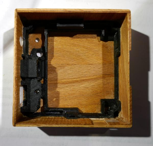 This is a view of the interior of the wooden enclosure. The black skeleton
is a 3D printed plastic part made for this to hold the rotary encoder the
knob is mounted to, and the alarm switch. Oh, and the coffee machine
connector.
This is a view of the interior of the wooden enclosure. The black skeleton
is a 3D printed plastic part made for this to hold the rotary encoder the
knob is mounted to, and the alarm switch. Oh, and the coffee machine
connector.
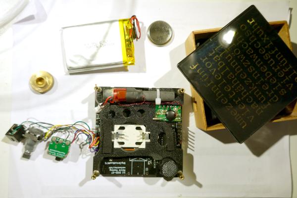 This is an overview of the parts. Starting at
11 o'clock and moving clockwise: the lipo battery, the CR2032 real-time clock
backup battery, the enclosure and face, the main electronics board, the
switches and connectors, and the knob.
This is an overview of the parts. Starting at
11 o'clock and moving clockwise: the lipo battery, the CR2032 real-time clock
backup battery, the enclosure and face, the main electronics board, the
switches and connectors, and the knob.
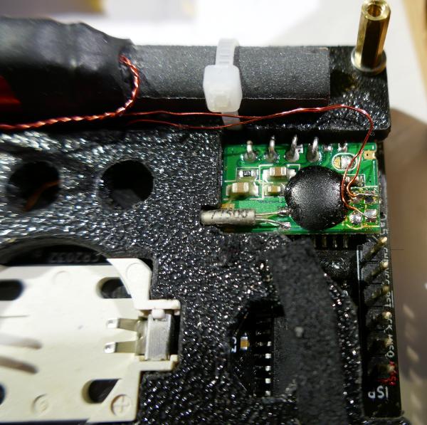 This is the smallest DCF77 radio clock receiver that I could find: from
Pollin.
Despite the size of its antenna, it has remarkably
good reception. OK, I'm really close to the DCF station, but compared to
other receivers I had used before, this one really was a positive
surprise.
This is the smallest DCF77 radio clock receiver that I could find: from
Pollin.
Despite the size of its antenna, it has remarkably
good reception. OK, I'm really close to the DCF station, but compared to
other receivers I had used before, this one really was a positive
surprise.
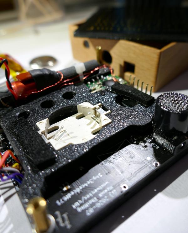 The black plastic part is the 3D printed inner base to which all the
inner stuff is mounted. Yes, I could have disassembled it more for more
detailed photos, but there needs to be something I can show when the two
final alarm clocks are finished.
The black plastic part is the 3D printed inner base to which all the
inner stuff is mounted. Yes, I could have disassembled it more for more
detailed photos, but there needs to be something I can show when the two
final alarm clocks are finished.
On the right, the buzzer is visible, and there is a metal mesh on it. This is a piece of tea sieve that I epoxied to it for protection against someone poking the coffee machine connector into the wrong hole.
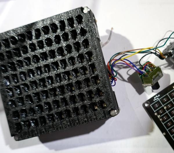
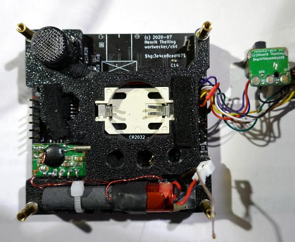 This is another overview of the electronics. Antenna on the bottom, and
the controls will end up at the top side.
This is another overview of the electronics. Antenna on the bottom, and
the controls will end up at the top side.
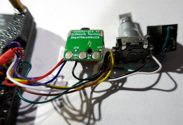 These are the controls: the alarm switch with a satisfying 'click' (yes,
I also did a switch selection session to find one with the right click
(that is small enough to fit into the clock)). Then the rotary encoder
with 30 positions and a push button, and the audio jack for the coffee
machine control.
These are the controls: the alarm switch with a satisfying 'click' (yes,
I also did a switch selection session to find one with the right click
(that is small enough to fit into the clock)). Then the rotary encoder
with 30 positions and a push button, and the audio jack for the coffee
machine control.
The alarm switch is mounted to another small PCB. This was the easiest way I found to put an LED in the right spot and to have a mounting hole for securing the switch.
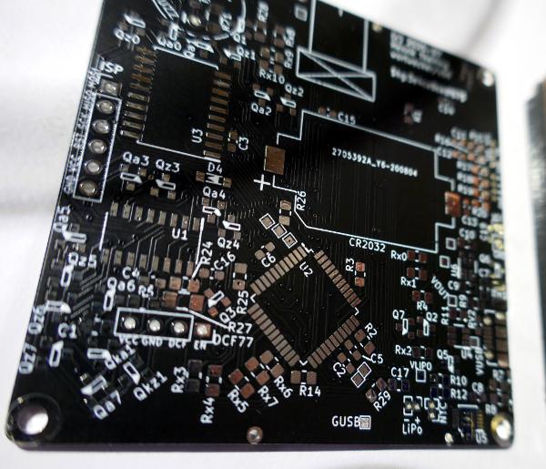 This is the empty PCB of the control board of the clock. I had this
manufactured by JLCPCB. The quality and
precision are really good.
This is the empty PCB of the control board of the clock. I had this
manufactured by JLCPCB. The quality and
precision are really good.
 This is the front side with 3D printed LED mask. It came out so ugly!
But it works like a charm and no-one can see it when the face is
attached to it.
This is the front side with 3D printed LED mask. It came out so ugly!
But it works like a charm and no-one can see it when the face is
attached to it.
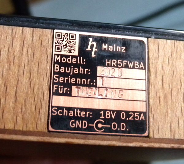 A bit later, I added a type plate to the bottom of the alarm clock. The
clock is model HR5FWBA: 'HR' for clock, '5' for the fifth clock model
that I built in my life, 'F' for radio-controlled ('Funk' in German),
'W' for word display, 'B' for battery driven, and 'A' for alarm clock.
A bit later, I added a type plate to the bottom of the alarm clock. The
clock is model HR5FWBA: 'HR' for clock, '5' for the fifth clock model
that I built in my life, 'F' for radio-controlled ('Funk' in German),
'W' for word display, 'B' for battery driven, and 'A' for alarm clock.
The type plate is also a PCB, which I had manufactured so that the text is etched in copper and everything is then completely covered with black solder mask. I sanded the solder mask down so the copper structure becomes visible. This way, no tin will cover the copper and finer structures are visible. The QR code is so finely manufactured that it actually works.
For writing the serial number, manufacturing year, etc., I used 1,5mm letter punches. I am not that good at punching yet; getting the force right is difficult.
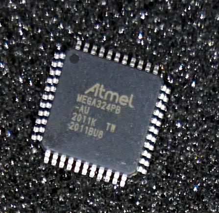 Finally, this is the controller I used: an Atmel atmega324pb 8-bit
micro-controller. As usual, to have more fun, I programmed it
completely in assembler. Due to the additional
logic for a low-power functions, and for
alarms, etc., this is 7kB of code (plus 1kB for tables for the display).
The wall clock uses only 4kB.
Finally, this is the controller I used: an Atmel atmega324pb 8-bit
micro-controller. As usual, to have more fun, I programmed it
completely in assembler. Due to the additional
logic for a low-power functions, and for
alarms, etc., this is 7kB of code (plus 1kB for tables for the display).
The wall clock uses only 4kB.
This battery powered circuit was really fun to do because it was a totally different kind of optimisation compared to what I had built before. The whole design is centered around low-power. I got it down to 15µA (measured right at the battery) when the clock is sleeping, i.e., including the sleeping µC, quiescent currents from the USB charge controller, the LDO, and all the other tiny things that all draw power.
The silent DCF reception draws around 600µA. This is needed once a day during the night for typically 80s if all goes well, and for up to 600s if there's no reception.
When the display is switched on, the clock draws between 5mA and 10mA, and the buzzer draws an additional 15mA.
With these numbers, I reckon the 1000mAh battery should last at least half a year, but actually more like a year. We'll see.
The CR2032 is the backup power for the real-time clock that I use (a DS3234 with an SPI bus because SPI draws less power than I2C). Using another battery may be overkill, but why not. This battery should last around 5 to 10 years, hopefully. The µC can monitor both batteries and will warn the user if one runs low.