| « 2019-05-26 | Tinkering | 2019-03-10 » |
Tinkering: 2019-04-14: Parallel Stops for Festool Guide Rail
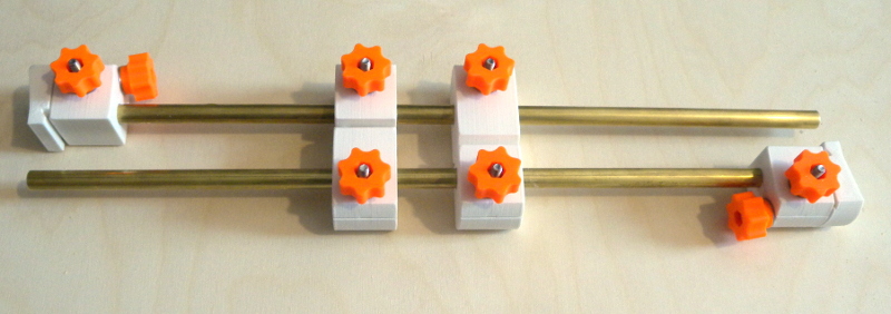
This 3D printed jig replaces Festool's FS-PA (Parallelanschlag), which is quite expensive and large (I have a small workshop). It is the simplest solution I could come up with that offers highly precise repeatability for multiple same width cuts. It allows same-width cuts at any width, limited only by the length of the rods that are used (Festool's jig is limited to 650mm).
The parallel stops are attachments for the guide rail and can be attached on both sides. They are optimised for small cuts, i.e., for the front side of the rails, because I found myself in more need to do this precisely.
The jig does not attempt to incorporate any way of measuring. Calipers and measuring tape should be available anyway. The main goal of this jig is exact repeatability. The jig does offer very good precision of front side cuts measured with calipers, however.
Attaching To Guide Rail
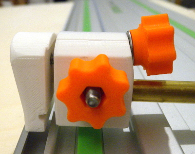
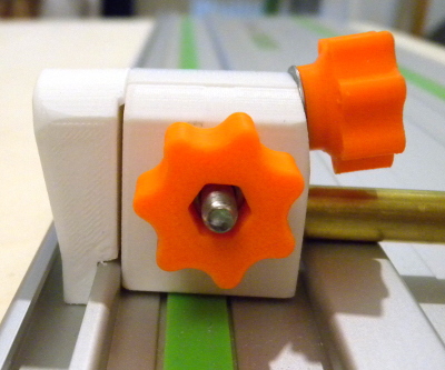
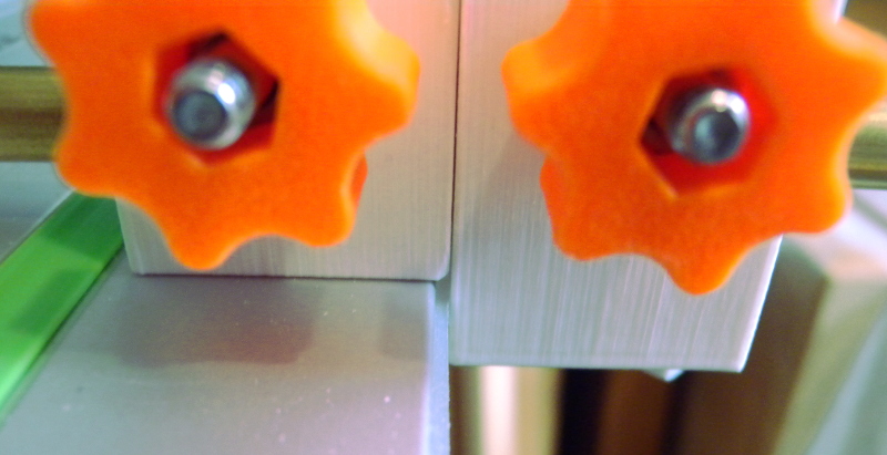
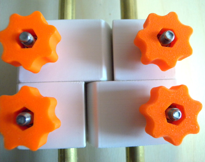
The jig is clamped to the guide rail using the skewed screw for fastening. The shape of the clip (particularly the lip at the top) causes the part to be pulled down a bit toward the rail so it becomes flat with the rail surface.
Front Side Cutting
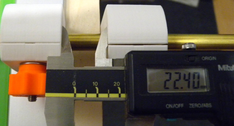
On the front side, the middle part is positioned exactly at the edge of the rails, where the saw blade cuts, so that the end stop slider's distance can be measured with calipers exactly. My blade cuts 2,4mm wide, so for a 20mm cut, I adjust the distance to 22,4mm.
Front Side Zero Position Calibration
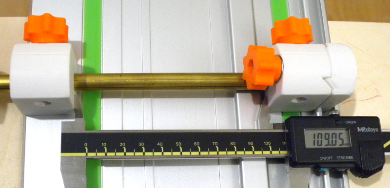
For exact front side calibration, the two sliders can be pulled out, pushed together, and then pushed against the rail's edge as one piece. The stopper will align exactly with the rail's edge to position the middle part exactly at this edge. The middle part can then be fastened.
The distance between the clamp and the middle part will be quite exactly 109mm. This is because the rail is 185mm wide (from back to the cutting edge), the t-slots are 16mm wide, the sliding parts are 30mm wide, and 185 - 16 - 2*30 = 109. Since this is a constant distance, this number is marked on the clamp (maybe it comes in handy one day).
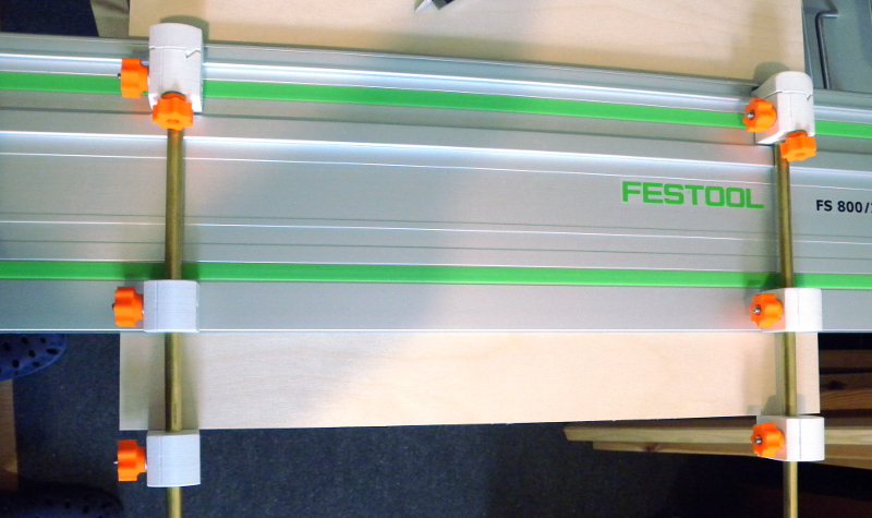
Back Side Cutting
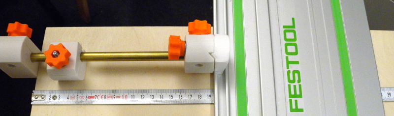
On the back side, the middle part is turned by 90° to lay flat on the object again. This part is not used for measurement on the back side, but only for stabilisation and support. Measuring can be done normally from the edge of the object to the cutting edge of the rails (e.g. with a measuring tape as shown).
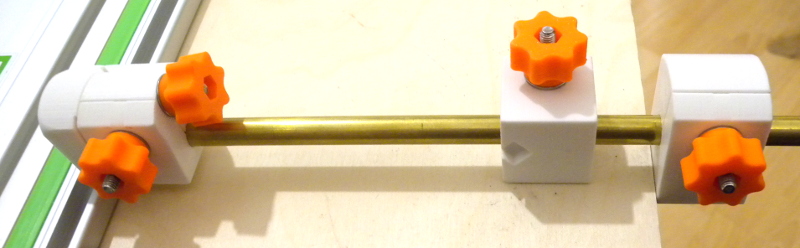
Left and Right Alignment
The two identical parts for left and right positioning have a notch and a peg so that they can be attached to each other. This is for copying a distance from one part to the other. After printing the jig, the pegs probably need to be filed down a bit to fit into the notches. It should be a snug fit, but not overly tight so that the parts can be deattached from each other without accidentally moving the sliders.
Also, it should be checked that the attached parts are a precise match by sanding or filing the pieces to minimise the irregularities and to close the gap between the connected parts. This may be a bit of precision sanding, but the reward is precise copying. My parts came out of the 3D printer quite OK, but an 0,2mm gap had to be dealt with.
Printing
The jig should be printed in the orientation of the STL files, because they are arranged cautiously.The parallel parts used for measuring the distance with calipers, which need the highest precision, will be on top. If the printer prints straight, the rod will end up exactly 90° with the top, and the typical small impurities at the top can be filed or sanded off easily. If your printer has an exactly plain bottom, an alternative would be to put the two involved parts upside down. My printer (Prusa MK3) has a textured surface, so I preferred it the way the parts are oriented in the STL.
The clip is oriented so that the clamping forces do not shear off the part between the printed layers.
Also, I tend to make holes in 3D parts a bit too small. So I drilled out all 5mm and 10mm holes until the fit was good. Particularly the fit on the rod should be good: snug so it can be tightened, but still easy to move.
I printed all this in ABS at 0.2mm layer height. Any material should be fine. At a larger layer height, the holes for the screw heads may need some cleaning, because the overhangs inside the holes are computed for 0,2mm layer height.
Bolts and Nuts
The following parts are needed in addition to the printed parts. These are all metric (I live in the metric part of the world).- 6 x M5x35 hex head screw, DIN933 (or DIN931); longer ones work, too, I used M5x40
- 2 x M5x50 hex head screw, DIN933 (or DIN931); longer ones work, too
- 8 x M5 large washer, DIN9021
- 8 x M5 hex nut, DIN934
- 2 x ca. 400mm (or longer) of 10mm round tube or rod (brass or aluminium or steel or plastic); M10 threaded rods may work, too, but as they bite into the plastic, they might harm precision and might wear out the plastic parts.
Future Improvements
At full plunge depth, the Festool circular saw comes down to the rail to leave only a very narrow space between the rail and the motor. The current jig cannot be left clamped to the rail for that reason even when mounted at the back side of the rail (at the front, it must be removed anyway, because it is mounted from the top where the saw will be). The clamp could be redesigned to be very flat and instead longer. But such a design would be more complicated.While back side cutting works well, for very wide cuts, the jig probably needs refinement to stay exactly rectangular so no skewing errors occur. This will be a future project and probably an extension or improvement of this one.
Download
All parts are available as SCAD and STL at Thingiverse, or here:fsanschlag.zip