| « 2019-01-25 | Tinkering | 2018-04-30 » |
Tinkering: 2018-09-23: 3D Printing Simplified To 2D Problems
For the past few weeks, I've been working on an idea I had for at least a year now to improve my 3D printing experience: I want to remove the need of converting the 3D model into a single polyhedron. The math behind this is complex and the resulting algorithms tend to be unstable for floating point operations. I often encounter unpredictable, frustrating, and undebuggable problems like with very long computation times, or error messages like 'this is not a valid 2-manifold'. OK, let's start at the beginning.
Introduction
When constructing a 3D model, a common technique is CSG, Constructive Solid Geometry, which is used in most modern CAD programs even if they do not require you to program in CSG manually (like you would do in OpenSCAD), but also if you draw stuff in a nice GUI. Under the hood, you get a tree of primitive objects that are combined by boolean operations, typically OR, AND, ANDNOT and on occasion XOR. (OpenSCAD calls them 'union', 'intersection' and 'difference' (and has no 'XOR' because it is kinda weird for solids).)
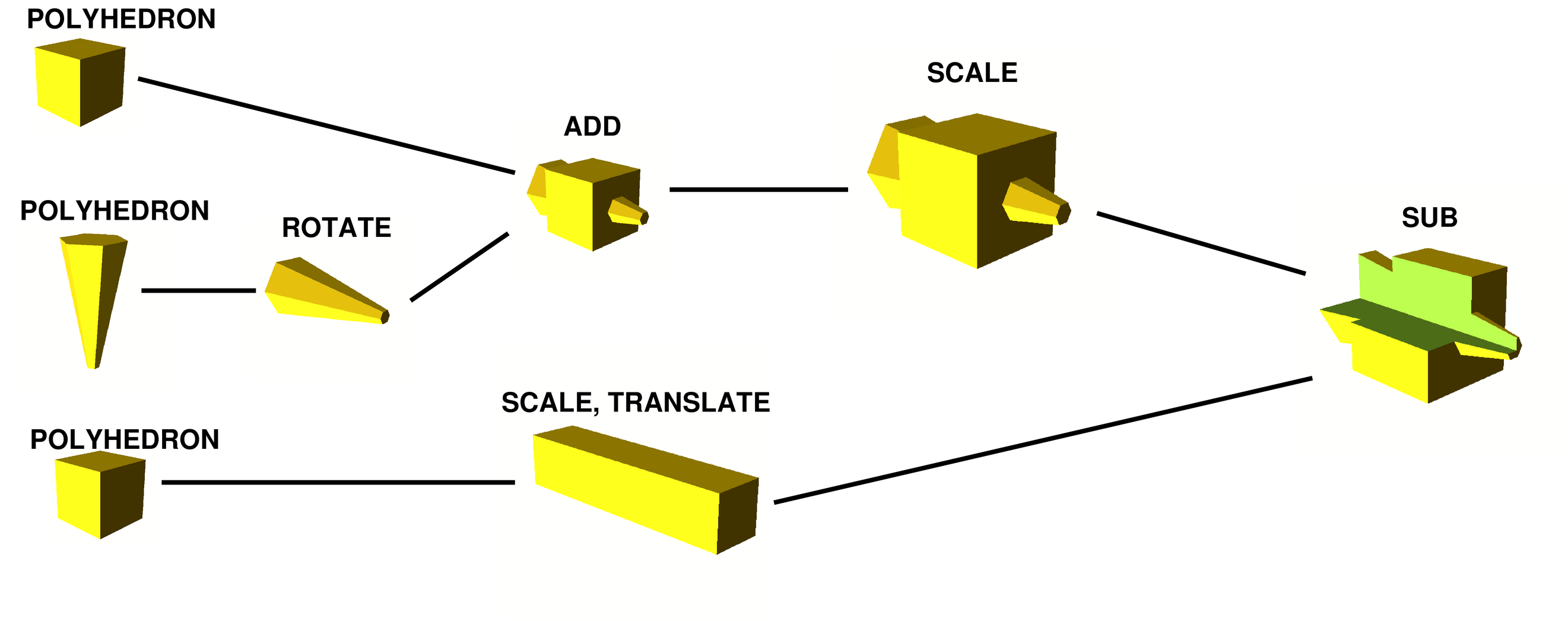
Actually, that picture is a preview already: in this data format, no polyhedra are stored nor computed anywhere except in the leaves, where the input solids are stored. What is really only stored is this:
In OpenSCAD format, it looks like this:
difference() {
    scale(2) {
        union() {
            cube([10,10,10], center=true);
            rotate([-90,0,0]) {
                cylinder(h = 20, d1 = 2, d2 = 10, center=true, $fn = 6);
            }
        }
    }
    translate([-5,0,5]) {
        scale([1.1,5,1.1]) {
            cube([10,10,10], center=true);
        }
    }
}
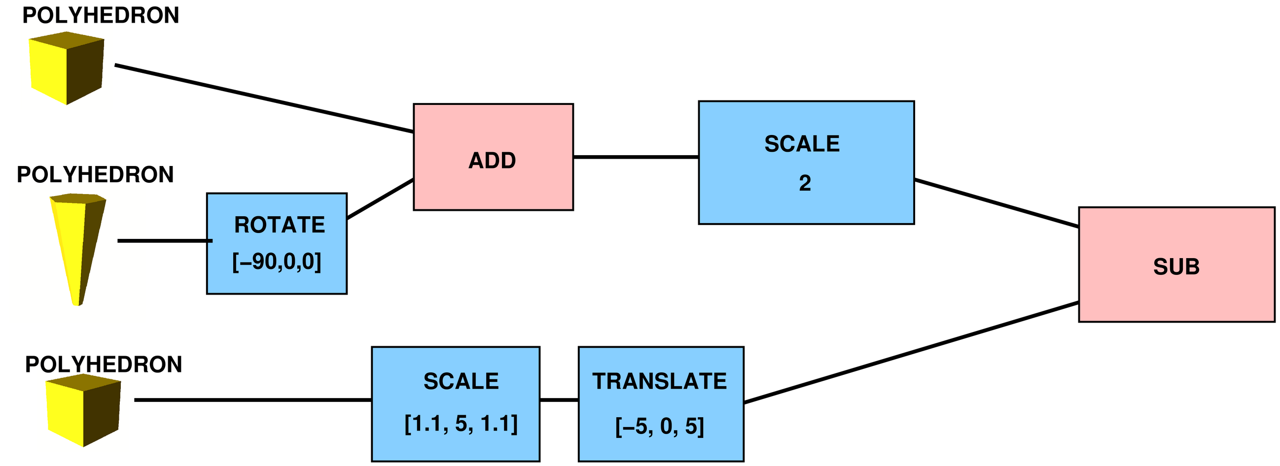
Looking more closely: the nodes are either leaves (with polyhedra), nodes with one child for transformations (translate, scale, rotate; shown in light blue), or are the actual CSG operations (sub, add, cut; shown in pink) with two children that are combined.
A small simplification for the rest of this article: since the transformations in the CSG tree are all matrix operations, they can be combined and pushed down to the leaves, across the CSG operations, and then applied to the leaves, without changing the result.
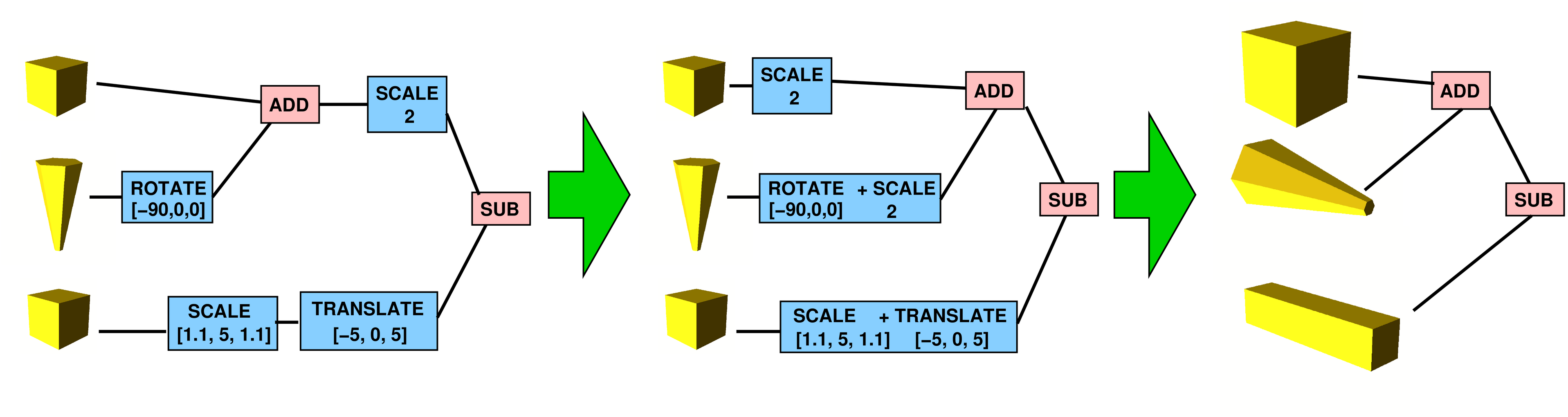
Because they are trivial and can be pushed out of our way, let's neglect those transformations for now, and focus only on the ADD, SUB and CUT operations.
The Single Final Polyhedron
In the 3D printing workflow, the next step is to reduce that CSG construction tree into a single polyhedron describing the resulting solid purely by 3D triangles on its surface.
My goal is to kick out this step from the workflow.
I want to kick it out because those 3D CSG operations are offendingly slow and computationally instable.
The operations are usually applied in the tree from bottom to top:
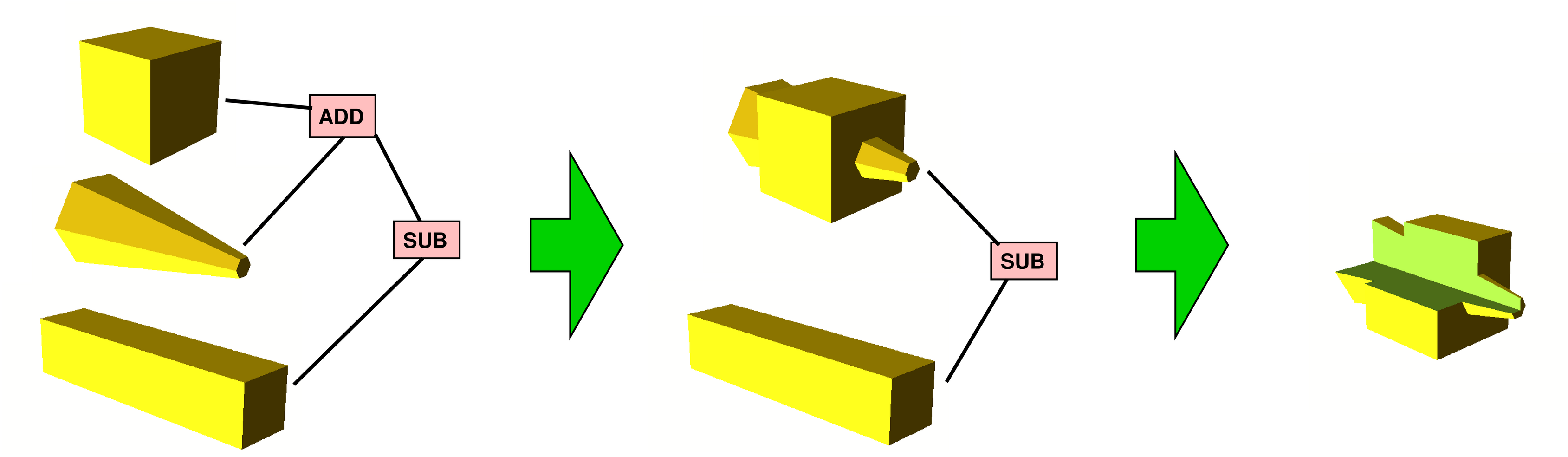
I am using OpenSCAD to do this, and it does its best to do this difficult step well, e.g. by using the CGAL library for precise real arithmetics to overcome a bit of the computational instability problem. But still, it is a difficult problem that is slow and fails spuriously. OpenSCAD usually cannot pinpoint where exactly it does not like the input – it just produces a global error message. Or it produces utter BS that the next step, the slicer, cannot read because the solid has holes or is otherwise misshaped.
So why are those CSG operations so complicated? Because 3D has a lot of orientational freedom, i.e., the combined polyhedra can be positioned in many ways relative to each other, and in many cases, a lot of smaller and smaller triangles need to be introduced to correctly map the shape of the resulting object. At the end, floating point arithmetics reaches its limits and a division by zero is encountered. Or an otherwise wrong result.
Comparing 3D to 2D, in 2D there is much less freedom of orientation, so I am hoping for much less computational instability.
The Slicer
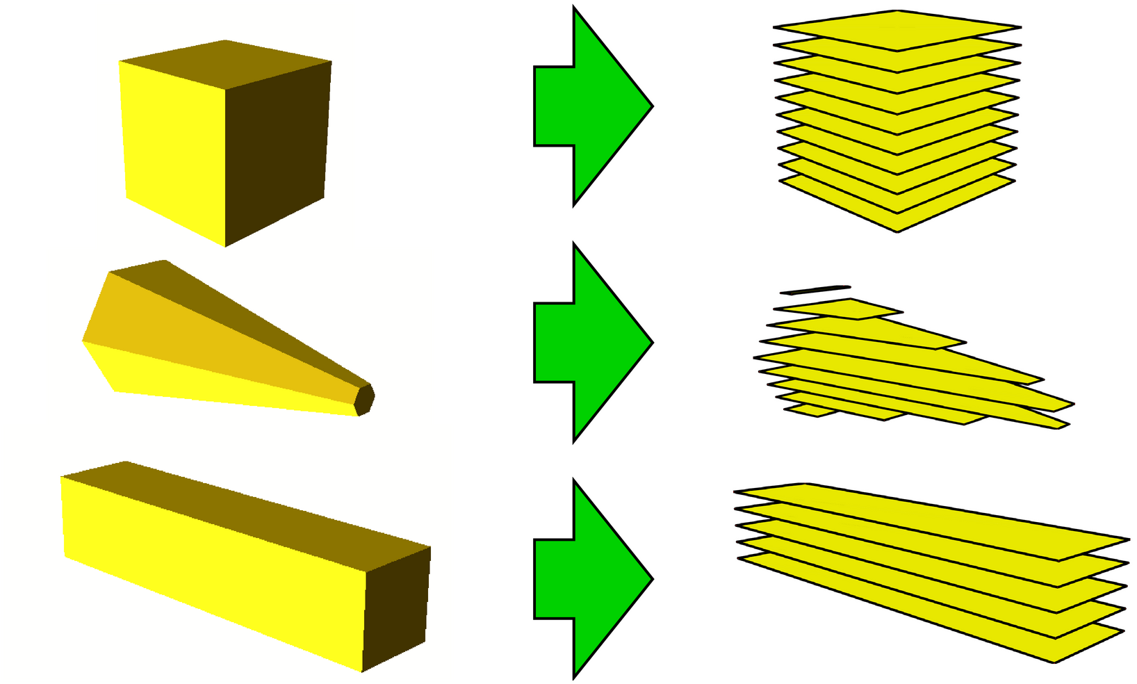
After the final polyhedron is computed, the resulting STL file containing the 3D triangles of the solid's surface are supplied to the 'slicer', which computes how the 3D printer will move. Since the 3D printer strictly prints layer by layer from bottom to top, the slicer will slice the solid into thin slices in this step, hence its name. E.g. 0.2mm thick slices will be printed. The slices are basically 2D parallel to the XY plane of the print table.
Slicers need to read the model in a simple polyhedron format, like STL, that we produced with Openscad. The first step is to slice this polyhedron into 2D slices.
Now, slicing that polyhedron is not a problem. It is relatively easy business, and slicers are not known to be particularly slow – when loading your model, typically after a few seconds, you have the output file with the GCode commands that the 3D printer speaks natively, i.e., you can print. The following is the print preview, where the stack of slices is visible, and one slice at 10.4mm from the bottom of the object is shown, too.
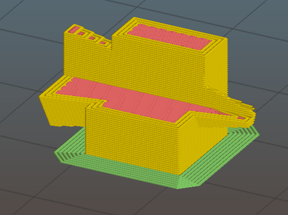
It can be seen that the slicer not only cuts slices, but computes print paths from it. This can be parameterized in various ways to set the thickness of the outer wall, the amount of infill, etc. All this is computationally stable and sound – that part works well, I do not want to change that.
From the beginning of my 3D printing tinkering, I always found it strange that the computationally complex intermediate step of computing a single polyhedron is needed just to then slice it into flat 2D polygons. This seemed like totally wrong. Overkill.
The Idea: Stacks of Slices of 2D CSG Trees
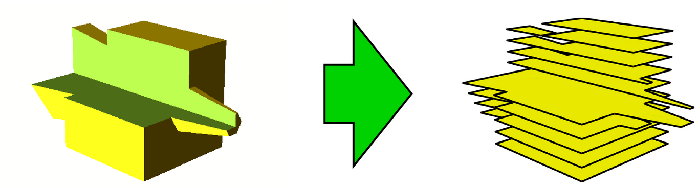
So my project of the past few weeks was to skip the previous step, and instead slice before applying the CSG technique, i.e., slice each input polyhedron in the leaves of the CSG tree, not the output polyhedron of the CSG technique, e.g.:
This can then be reinterpreted as one 2D CSG tree per layer, which can be solved into a polygon (well, maybe multiple polygons). The result should be the same or at least very similar to the 3D technique after slicing, only I will already get a sliced result. This can then be fed into the slicer somehow, which would only need to compute print paths from this. (The slicer I use has no appropriate input format for this, so I will re-convert the 2D slices to 3D by extruding them to the layer thickness and store them as STL file. That's not perfect, but works and is relatively straightforward, fast, and stable.)
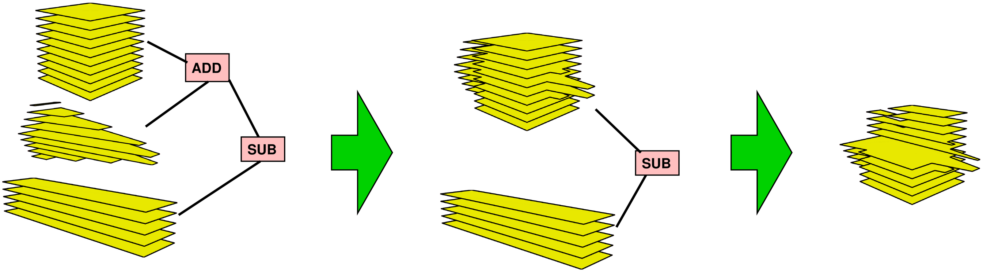
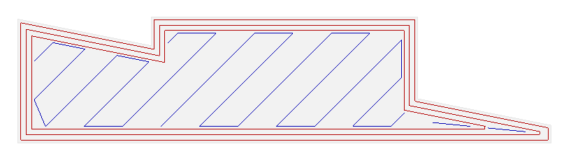
This way, the 3D CSG is reduced to polygon clipping (OK, arbitrary polygon boolean operations, but that's really equivalent). Polygon clipping is much less ugly and much more stable than 3D polyhedra boolean operations. We will end up with one 2D CSG problem per layer, e.g. one layer would look as follows:
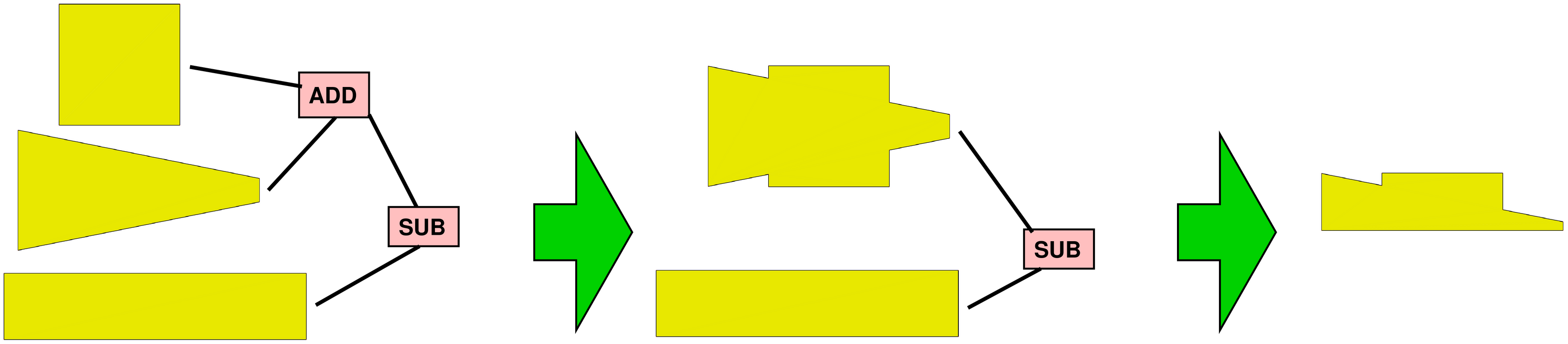
OK, there will usually be hundreds of those layers, but intuitively, it really cannot be slower than the CSG 3D rendering, because that is really, really slow. And, as I said, at the very least my 2D method should be much more stable wrt. floating point operations.
Actually, I do not need hundreds of 2D trees, at least not as separate data structures, because the boolean operations will be the same in each layer. Only the solids will be sliced differently so we will get different sets of polygons. The main combinatorial tree of the CSG model can be shared among all layers.
Implementation
Now, I started programming. I abstained from inventing a new file format, although that was hard. I reused .scad and .stl and for debugging, PostScript.
After implementing three major algorithms, the first version of my tool is ready. The three algorithms are:
- The initial slicing extracts 2D polygon paths from a given 3D CSG tree. The result is a 2D CSG tree that has, instead of 3D polyhedra, stacks of 2D polygons. I implemented this algorithm without any paper because I thought it was relatively straightforward.
- The 2D CSG application ('clipping') algorithm. I used a paper of Martínez, Rueda and Feito (2009) for boolean operations on (almost) arbitrary polygons.
- The 2D triangulation of the resulting polygons, which is needed to write STL format. I used a paper of Hertel and Mehlhorn (1983) to implement this. The algorithm had to be extended to handle the output of the previous algorithm (I cannot exclude coincident vertices).
I can already read simple .scad files (with all the basic stuff, but no syntactic sugar). I can slice the 3D objects into 2D polygons, apply the 2D boolean operations and triangulate them. Basically all I need. I can dump the stuff for debugging in .ps format which I can convert to .pdf for convenience.
My tool uses standard 'double' floating point arithmetics instead of CGAL, because I figured that 2D will be so much more stable that I do not need a better real type. Indeed, I did not encounter any problem when doing stuff properly (e.g., always caring about a configurable 'epsilon' in comparisons to prevent instability). It seems to work well.
And, on a real-world example from my 3D printing constructions, I measured that my technique is over 100 times faster (this value tends to change while I improve the algorithm and hunt down bugs) than the 3D CSG modelling (0.35s vs. 53s) on a single core. In this example, the tool needs to cut 170 slices, i.e., applying 170 times the 2D CSG algorithm to the model (slice + clip + triangulate) is 100 times faster than applying CSG a single time in 3D. That's much better than I had hoped for.
And I am only just starting to optimise: the 2D technique is perfectly suited for parallelisation because each slice is independent from the next, so multiple threads can process slice after slice independently and will not interfere at all. Also, the internal 2D CSG algorithm should be able to handle more than two polygons at the same time: running the algorithm once with more vertices should be faster than running it multiple times.
Finally, the major fun part of implementing those algorithms was dealing with corner cases: vertices right on another edge, coincident vertices in the same/in different polygons, intersecting collinear edges, polyhedra touching each other in exactly one point/edge/face under different operations (ADD, SUB, CUT), etc. The basic algorithms are usually not overly complicated, but the main work is to get those corner cases right. I plan to dedicate another article to this, because my major goal was stability, and without proper handling of corner cases, the technique cannot be stable nor predictable.
Download
The source code is available on Github.