| « 2018-01-10 | Tinkering | 2017-12-23 » |
Tinkering: 2018-01-04: The Time Line
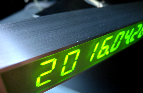 The Time Line clock is a clock design I made for our living
room, with the design goal of using a very simple digital (but easily
human readable) way of showing the time (and the date). The simplest
in this sense is a row or line of 7-segment LED displays.
The Time Line clock is a clock design I made for our living
room, with the design goal of using a very simple digital (but easily
human readable) way of showing the time (and the date). The simplest
in this sense is a row or line of 7-segment LED displays.
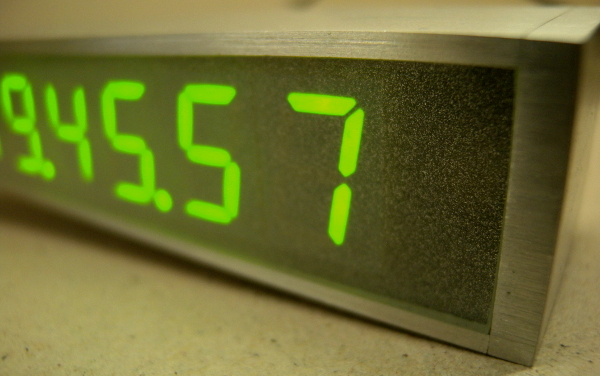
To further stress simplicity, digitality, and the technical representation of time as integer numbers, I thought it would be nice to be close to a simple counter of seconds. It should be possible for everyone to read the clock naturally, so since the standard time and date are not a simple decimal integer that counts up, what can be done is to show the date in Japanese format (YYYY-MM-DD) followed by the time (HH-MM-SS). This way, digit changes propagate from right to left, with the right-most digit the fastest changing and the left-most digit the slowest, like in an incrementing integer. Of course the 24h format is used for the time, not the 12h AM/PM format (where 12am is before 1am).
As usual, the clock has no way of setting it. Buttons are just unnecessary warts. This is a design goal, too. Because the clock should be the device that knows the time and tells me that. I think it is strange that first I have to tell the clock what time it is in order for it to tell me what time it is later. That concept feels wrong. So all my clock designs are either radio controlled or have other means to just know the time (e.g., an internet connection, GPS, you name it). This clock will use the DCF77 time code radio signal available in Europe. It will be fixed to CET/CEST time zone (Central European).
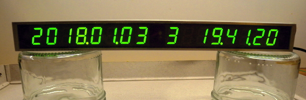
Now, with the DCF77 signal and a digital clock, I added design goals to show all time/date info available, i.e., the day of the week, the time zone (CET or CEST), and to have an indicator of the DCF77 input signal. Since I want 7-segment LED digits without any extravagance, the week day will be shown as an integer between 1 and 7 between the date and the time. This is clearly a concession to the digital design simplicity, while hurting natural readability. Decisions need to be made.
CEST ('summer time') will be shown as a single dot behind the week day. That dot will be switched off during CET ('winter time'/'normal time').
The DCF77 input signal will be shown as received, as a blinking dot behind the seconds. With this, the radio reception can be checked when placing the DCF77 receiver module.
Now, DCF77 allows for precise implementation of both summer/winter time switching and for insertion of leap seconds. Since this clock, in contrast to the About-O-Clock, has a seconds display, my DCF77 clock library had to be improved to support all this. This is now the only radio-controlled clock in our home that can do both time zome switching and leap seconds correctly – all other (commercial) clocks will just ignore the two bits from the DCF77 signal and correct themselves a few minutes after the event. This clock will instead correctly run up to 00:59:60 (or 01:59:60) and then switch to 01:00:00 (or 02:00:00) when a leap second is inserted. (Mind you, leap seconds are always inserted at midnight UTC, so that's 1 o'clock in winter or 2 o'clock in summer on this clock.)
Finally, a small, plain, elegant, bar-shaped aluminium casing, preferably brushed and without any ornaments, should underline the simplicity.
And the colour of the LEDs? I had some heated discussions with my wife about that. I had used yellow/orange (595nm) for a clock before, and it is truly a lovely colour. For this project, however, I wanted something different, because the technical look dictates something colder. RGB is clearly against the principle of simplicity, of course. Luckily, I also did not find 7-segment RGB displays so this was not an option anyway. Blue or white would be OK, but those LEDs are overused at the moment, for my taste. These colours where special when they arrived (several decades after red, yellow, and green), and then they got used everywhere being special and cool. For this reason, this project uses green LEDs, the coldest of the original LED colours. I did not find cyan or turquoise 7-segment LED displays, otherwise, the story could have ended differently.
 This clock is an antithesis of the About-O-Clock, which is imprecise, warm, large, and
uses words instead of digits. The clocks oppose each other in our
living room. Wrt. design goals, however, the clocks share elegance
and simplicity, and the focus on telling the time without distraction.
This clock is an antithesis of the About-O-Clock, which is imprecise, warm, large, and
uses words instead of digits. The clocks oppose each other in our
living room. Wrt. design goals, however, the clocks share elegance
and simplicity, and the focus on telling the time without distraction.
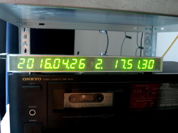 The About-O-Clock hangs on the wall like a
picture, while the Time Line is placed in a sheet metal rack
containing media players, so the style fits quite nicely, I think.
The About-O-Clock hangs on the wall like a
picture, while the Time Line is placed in a sheet metal rack
containing media players, so the style fits quite nicely, I think.
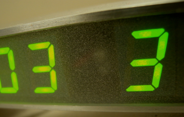
This picture shows the summer time indicator: the dot behind the week day: '2.' for 'Tuesday, CEST'. In contrast to that, the previous picture shows '3' (without dot) for 'Wednesday, CET'.
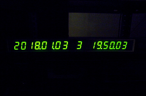 The brightness adjusts automatically, so it is not too bright at night.
If you are wondering about the elapsed time of almost two years, well, the clock needed a firmware update recently, because I had noticed a major bug concerning communication with the MAX display drivers and I had feared burning of LEDs, i.e., hardware destruction (see below). A firmware update means partial disassembly, so I used the opportunity to take more photos for this report.
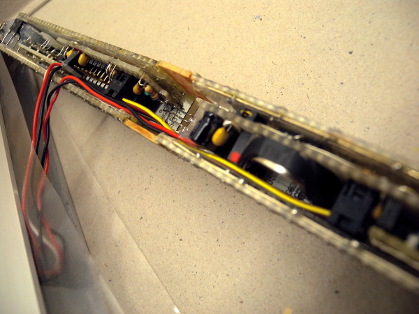
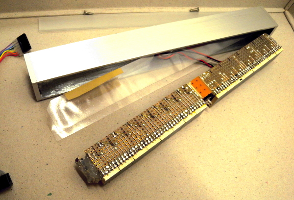 The biggest challenge in this project was to fit the electronics into
the small aluminium U bar that I had bought. I wanted it in there
without compromise so it would look good, and the U bar was only
available in so many sizes. I had chosen one that should,
theoretically, just be large enough based on the size of the LED
displays that I had bought for this. A millimeter more or maybe two
would have been comfortable and acceptable, design-wise, but was not
available, only 5mm more was. So the single most important building
tool became the mighty Dremel, which acted as the persuader for the
electronics to fit into the casing. In the end, it took a lot of
persuading. And some resoldering after too much persuading... You will
see throughout the photo set that almost everywhere, there are remnants
of persuasion.
The biggest challenge in this project was to fit the electronics into
the small aluminium U bar that I had bought. I wanted it in there
without compromise so it would look good, and the U bar was only
available in so many sizes. I had chosen one that should,
theoretically, just be large enough based on the size of the LED
displays that I had bought for this. A millimeter more or maybe two
would have been comfortable and acceptable, design-wise, but was not
available, only 5mm more was. So the single most important building
tool became the mighty Dremel, which acted as the persuader for the
electronics to fit into the casing. In the end, it took a lot of
persuading. And some resoldering after too much persuading... You will
see throughout the photo set that almost everywhere, there are remnants
of persuasion.
 In the end, I think, it was worth the effort: it may well be that even
a millimeter more space would not have been as nice as it looks now.
In the end, I think, it was worth the effort: it may well be that even
a millimeter more space would not have been as nice as it looks now.
Also, I was very lucky to find the right finish for the front in a nearby copy shop, a sticky matte sheet of plastic glued on the inside of the acrylic glass front. It has just the right grain size and exactly the right level of transparency, I think. This completely resolved my initial worries about a fitting diffusor.
 The casing is an aluminium U profile, 30mm deep and 25mm
high, leaving 21mm for fitting the electronics. I cut it to length
and glued a piece of 4mm thick aluminium on the ends with epoxy glue,
to get a casing that is open only at the front. As already mentioned,
the front is a 2mm acrylic glass sheet that is cut and filed to a snug
fit so that it does not fall out. It is held in place purely by friction.
The depth of the electronics is such that the acrylic glass ends up
exactly flush with the aluminium.
The casing is an aluminium U profile, 30mm deep and 25mm
high, leaving 21mm for fitting the electronics. I cut it to length
and glued a piece of 4mm thick aluminium on the ends with epoxy glue,
to get a casing that is open only at the front. As already mentioned,
the front is a 2mm acrylic glass sheet that is cut and filed to a snug
fit so that it does not fall out. It is held in place purely by friction.
The depth of the electronics is such that the acrylic glass ends up
exactly flush with the aluminium.
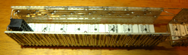
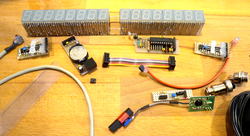 The guts of the clock are built from a series of PCBs that are put
together like a sandwich, with the LED display PCBs bracing
the rest.
The guts of the clock are built from a series of PCBs that are put
together like a sandwich, with the LED display PCBs bracing
the rest.
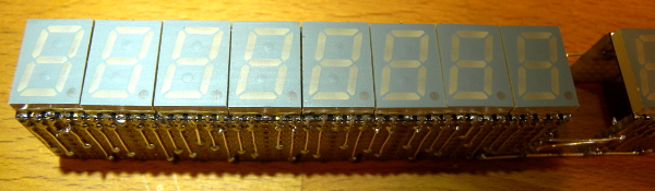
There are 16 7 segment LED displays with a gap in the middle of exactly the width of one 7 segment display, so the whole block is 17 times an LED display wide. The LED module is the large module in the top part of the picture.
16 LED displays means it is 2 times 8, and each group of 8 is controlled by a MAX7221 chip. It is the first time I use this integrated display controller – the About-O-Clock uses a custom built constant current source controlled by the CPU instead. The MAX chips are smaller and do not require the CPU to have many pins. For each of these MAX chips, there is a controller module, shown right below each end of the LED module.
Two more modules are going to be fitted into the small aluminium U profile, one is the real-time clock (RTC) with a backup battery, the other is the main CPU module.
The final bit is the DCF77 long wave time code receiver, which will be put in a separate plastic casing, to have better reception, and to allow for replacing the DCF77 receiver with a different antenna one day, maybe, and in order to be able to position the antenna independently from the clock itself.
Circuit
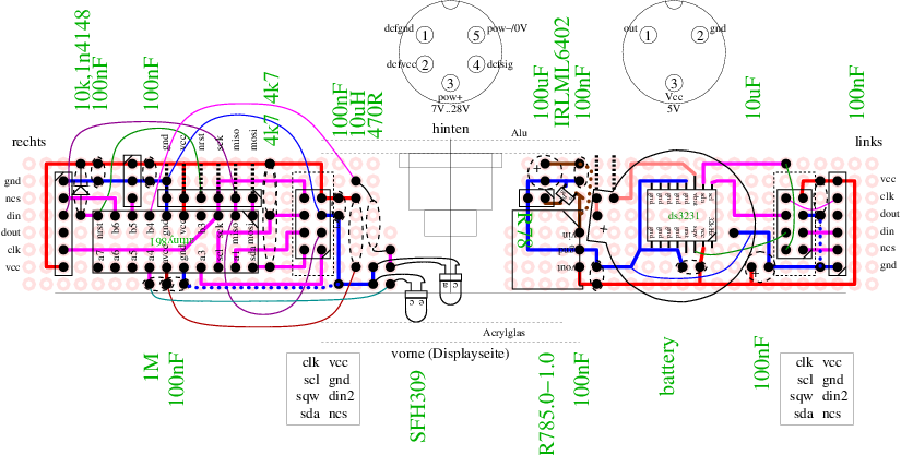 The RTC used here is a Maxim DS3231 chip, which is a temperature
compensated quartz clock with an expected precision of 2ppm, which
corresponds to an error of about 1 second every 6 days. This is an
improvement over the DS1307 I had used previously in the About-O-Clock, which requires an external quartz
and hence manual management of the precision of it. The bus is I2C
and the protocol is basically the same for both chips, so
wrt. connecting to the CPU, not much changes.
The RTC used here is a Maxim DS3231 chip, which is a temperature
compensated quartz clock with an expected precision of 2ppm, which
corresponds to an error of about 1 second every 6 days. This is an
improvement over the DS1307 I had used previously in the About-O-Clock, which requires an external quartz
and hence manual management of the precision of it. The bus is I2C
and the protocol is basically the same for both chips, so
wrt. connecting to the CPU, not much changes.
To allow for temperature compensation, the quartz is already on-board the DS3231, which is really nice, as it simplifies the design of the circuit. The only drawback is that the chip is only available in a SOIC package, the small size of which somewhat complicates manual soldering compared the usual DIL package, but the pinout is reasonably simple to allow manual soldering. In fact, SOIC means this chip is small enough to be fitted on the back side of the PCB below the battery, saving precious space in my design. A DIL chip, even an 8-pin chip like the DS1307, would probably not have fitted into my casing.
To put the precision of the DS3231 in perspective: John Harrison's 'Clock B' is about 17 times more precise, or less than 1 second in 100 days. It is amazing that this is possible for a mechanical clock! But it is also quite cool to be able today to just go and buy a fully integrated microchip the size of a fingernail for a euro or so that has such a high precision out of the box.
This clock uses the DS3231 for battery backup of time keeping, and it tries to query the current time at reboot when the time from the DCF77 is not yet available. It also uses the DS3231 for a seconds pulse, which drives the time that the CPU maintains. So without the DCF77, the DS3231 defines the precision of this clock. Usually, of course, the DCF77 signal can be used all the time to resynchronise, so it is highly unlikely that this clock is off by even a second.
DCF77 Receiver
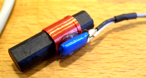 This is the DCF77 antenna. It is currently the smallest and cheapest
that I could find. In Germany, with the DCF77 time code transmitter in
Mainflingen practically right under our noses, reception should be more
than OK with this.
This is the DCF77 antenna. It is currently the smallest and cheapest
that I could find. In Germany, with the DCF77 time code transmitter in
Mainflingen practically right under our noses, reception should be more
than OK with this.
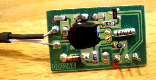 This is the DCF77 receiver module I got with the antenna. It
demodulates the binary pulses from the 77.5 kHz radio signal, and
provides them as an open collector signal. The pulses are 0.1s long
for a 0 and 0.2s long for a 1, and the CPU will decode this in an
edge-triggered interrupt (both edges).
This is the DCF77 receiver module I got with the antenna. It
demodulates the binary pulses from the 77.5 kHz radio signal, and
provides them as an open collector signal. The pulses are 0.1s long
for a 0 and 0.2s long for a 1, and the CPU will decode this in an
edge-triggered interrupt (both edges).
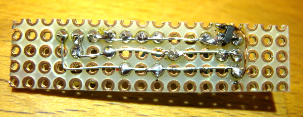
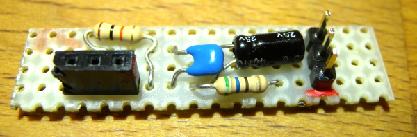 This is the front side of the small PCB I made for the DCF77 module. It
is just an additional voltage stabilisation.
This is the front side of the small PCB I made for the DCF77 module. It
is just an additional voltage stabilisation.
 This is the
back side of the DCF77 PCB. You may notice a small black thingy
soldered between three copper pads on the right upper side of the
picture. This is a very low resistance MOS transistor used for
reverse current protection. It acts as a diode, exploiting that
MOS transistors all have an implicit diode between source and drain.
Being MOS technology, it has no voltage drop compared to a normal
diode, but behaves like a resistor instead. It is a P-MOS
IRLML6402 transistor with a very low resistance of only around
65mΩ.
This is the
back side of the DCF77 PCB. You may notice a small black thingy
soldered between three copper pads on the right upper side of the
picture. This is a very low resistance MOS transistor used for
reverse current protection. It acts as a diode, exploiting that
MOS transistors all have an implicit diode between source and drain.
Being MOS technology, it has no voltage drop compared to a normal
diode, but behaves like a resistor instead. It is a P-MOS
IRLML6402 transistor with a very low resistance of only around
65mΩ.
Manually soldering this SMP transistor was a pain, but again has the advantage of taking up almost no space on the PCB.
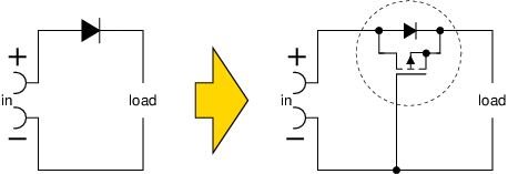 This is one of my favourite new tricks I learned in this project: to
have a reverse current protection without voltage drop from a diode.
I found it in an application note for battery protection circuits
from Texas Instruments.
This is one of my favourite new tricks I learned in this project: to
have a reverse current protection without voltage drop from a diode.
I found it in an application note for battery protection circuits
from Texas Instruments.
RTC and Power Regulator
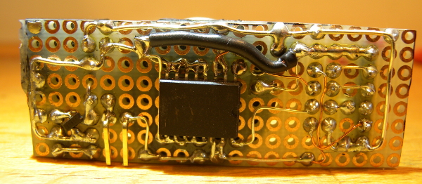 The same reverse current protection was applied to the RTC module (in
the lower left part of the picture), which also has the voltage
regulator of the clock and hence the power supply connector.
The same reverse current protection was applied to the RTC module (in
the lower left part of the picture), which also has the voltage
regulator of the clock and hence the power supply connector.
This picture also shows the DS3231 clock chip, which is too small for individual copper pads, so two of the pins are bent upwards and connected using my legendary 3D soldering technique. Luckily, about half of the pins are GND, and the chip does not have many pins we need: Vcc, VBat, I2C bus (two lines), and the signal for the seconds pulse that is used to drive the main CPU time keeping.
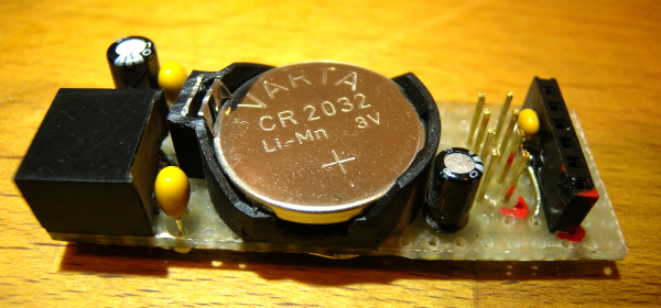 This is the front side of the RTC module, with its dominating battery.
That a small battery would be a major space issue was a new thing for
me. I had to carefully select the battery holder to make this work.
Still, as you can see, I had to Dremel off part of the battery holder
on the top, the front, and the back to make it flat and narrow enough
to fit.
This is the front side of the RTC module, with its dominating battery.
That a small battery would be a major space issue was a new thing for
me. I had to carefully select the battery holder to make this work.
Still, as you can see, I had to Dremel off part of the battery holder
on the top, the front, and the back to make it flat and narrow enough
to fit.
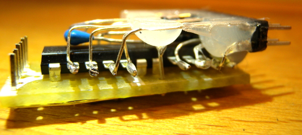
For simplicity and space constraints, I used a relatively expensive integrated DC-DC voltage regulator, a Recom R785.0. That's the large black box on the left. It is a drop-in replacement for a standard 7805. It is shorter, lacking a heat sink, and it requires fewer additional components in the circuit. Still, I also had to trim that voltage regulator a bit, but that's not visible in these pictures. As a bonus, this voltage regulator is very efficient, so that this clock draws only minimal power (well less than 1W from 230V mains).
The two electrolytic capacitors where also selected based on their physical size (mainly their height).
The CPU connects via a flat cable on the 4x2 pin header, which, you may notice, lacks its shaping plastic bottom, which I needed to remove, because, you guessed it, there is no space for that. Accordingly, its pins are trimmed, too.
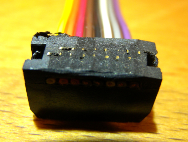 Finally, this is the connector that attaches to the pin header, and again,
it had to be dremelled off a bit to fit.
Finally, this is the connector that attaches to the pin header, and again,
it had to be dremelled off a bit to fit.
CPU Module
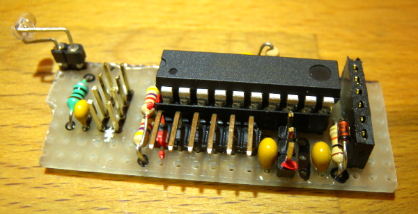 This is the CPU module, carrying an Atmel AVR attiny861. There is the same
pin header stunt as before, for the other end of the internal PCB connector. The
ambient light sensor can be seen on the left. The newest version also adds
an error indicator LED here, which the version in this photograph still lacks.
The 1x6 rectangular pin header in front is the programming connector. I prefer
it over the Atmel 2x3 standard pin header because it occupies less space and it is
usually easier to route, because magically, the pins from the chip are
just in the right place (at least for atmega8, atmega16, and attiny861 pinouts).
This is the CPU module, carrying an Atmel AVR attiny861. There is the same
pin header stunt as before, for the other end of the internal PCB connector. The
ambient light sensor can be seen on the left. The newest version also adds
an error indicator LED here, which the version in this photograph still lacks.
The 1x6 rectangular pin header in front is the programming connector. I prefer
it over the Atmel 2x3 standard pin header because it occupies less space and it is
usually easier to route, because magically, the pins from the chip are
just in the right place (at least for atmega8, atmega16, and attiny861 pinouts).
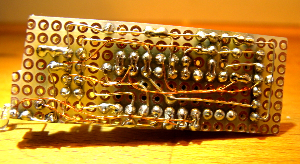 This is the boring back side of the CPU module without any SMD stunts.
Still, some dremelling can be spotted on the right where the main
power connector will need space.
This is the boring back side of the CPU module without any SMD stunts.
Still, some dremelling can be spotted on the right where the main
power connector will need space.
LED Driver Modules
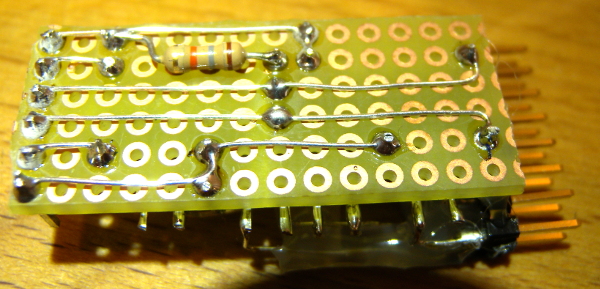
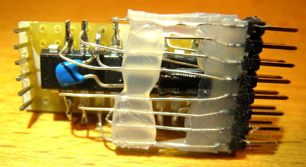 Now for some more 3D soldering: this is one of the two LED driver modules with
the MAX7221 in its center. Because this module connects at a 90 degree angle
to the LED module, I thought it would be wise to not waste space and do some
3D routing for connecting the pin header to the chip.
Now for some more 3D soldering: this is one of the two LED driver modules with
the MAX7221 in its center. Because this module connects at a 90 degree angle
to the LED module, I thought it would be wise to not waste space and do some
3D routing for connecting the pin header to the chip.
 This is the very boring back side of the LED driver PCB. The current
limiting resistor is also visible here. As already mentioned, I had
some problems communicating with the MAX7221 chips reliably. In another project where I am using the chips, I had
the same problem: bits are sometimes inverted, it
seems, and the MAX chip will misinterpret a command sent to it. This
particular clock circuit would sometimes switch decoding to BCD mode,
for example, while I had initialised it to direct mapping of bits. When
this happens, the display shows completely bogus hexadecimal digits.
Also, sometimes the brightness command is erroneously identified and
the display becomes much brighter than it should be.
This is the very boring back side of the LED driver PCB. The current
limiting resistor is also visible here. As already mentioned, I had
some problems communicating with the MAX7221 chips reliably. In another project where I am using the chips, I had
the same problem: bits are sometimes inverted, it
seems, and the MAX chip will misinterpret a command sent to it. This
particular clock circuit would sometimes switch decoding to BCD mode,
for example, while I had initialised it to direct mapping of bits. When
this happens, the display shows completely bogus hexadecimal digits.
Also, sometimes the brightness command is erroneously identified and
the display becomes much brighter than it should be.
 I had feared that one day, the chip would decide to switch the display width
from 8 digits to, say, 1 digit, which would mean current through the LEDs would
be 8 times as high. This could have burned the LEDs.
I had feared that one day, the chip would decide to switch the display width
from 8 digits to, say, 1 digit, which would mean current through the LEDs would
be 8 times as high. This could have burned the LEDs.
For this reason, I applied a firmware patch that reprograms all registers of the MAX chip in each display update cycle, which occurs at least twice a second. And that was the opportunity to shoot a few more pictures of the clock's guts.
LED Module
 This is the front of the LED sandwich brace.
 The LED modules are also SMD and they are held in place only by the
solder connecting them at a 90 degree angle.
The LED modules are also SMD and they are held in place only by the
solder connecting them at a 90 degree angle.
 This construction is quite fragile and can be damaged easily when
squeezing the sandwich at the open side.
This construction is quite fragile and can be damaged easily when
squeezing the sandwich at the open side.
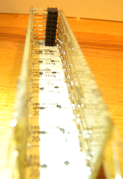
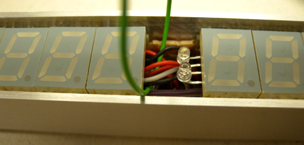
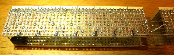 In this picture on the right, it can be seen that the left and right
parts of the LED module are connected only by a few soldered wires.
This turned out to be too instable and at one point, I bent the module.
In this picture on the right, it can be seen that the left and right
parts of the LED module are connected only by a few soldered wires.
This turned out to be too instable and at one point, I bent the module.
 This is why I then put in another small piece of PCB and glued together
the left and right parts.
This is why I then put in another small piece of PCB and glued together
the left and right parts.
This picture also shows both the ambient light sensor and the error indicator LED. They look exactly the same.
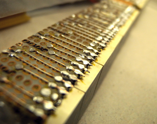 This detailed view of the LED module shows that I had to dremel off every
solder point, and even some of the copper wires to make the sandwich fit
into the casing. At this point, some accidents happened and made
repairs necessary...
This detailed view of the LED module shows that I had to dremel off every
solder point, and even some of the copper wires to make the sandwich fit
into the casing. At this point, some accidents happened and made
repairs necessary...
Sandwich Construction
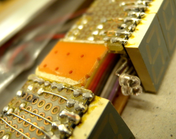
 The modules are fitted into the LED module like a sandwich. To
protect against shorts, there are insulating plastic sheets between the
PCBs.
The modules are fitted into the LED module like a sandwich. To
protect against shorts, there are insulating plastic sheets between the
PCBs.
 With a lot of patience, a steady hand, and more layers of insulating
plastic, the sandwich can be fiddled into the aluminium casing.
With a lot of patience, a steady hand, and more layers of insulating
plastic, the sandwich can be fiddled into the aluminium casing.
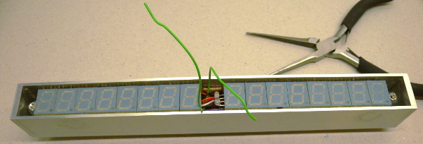
 To get the power and DCF77 signal wires into the casing, an auxiliary thread
or wire is necessary to pull them exactly into the small cavity that is kept
empty for them. The wires cannot be shorter, because the power/DCF77 connector
is secured from the inside of the casing with a nut so that no nut is visible
on the outside.
To get the power and DCF77 signal wires into the casing, an auxiliary thread
or wire is necessary to pull them exactly into the small cavity that is kept
empty for them. The wires cannot be shorter, because the power/DCF77 connector
is secured from the inside of the casing with a nut so that no nut is visible
on the outside.
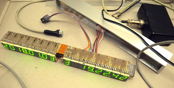 This is a test with the clock still open: it seems to work! In the background,
the black DCF77 receiver plastic casing can be seen. It is admittedly clunky, but
is meant to be hidden away anyway.
This is a test with the clock still open: it seems to work! In the background,
the black DCF77 receiver plastic casing can be seen. It is admittedly clunky, but
is meant to be hidden away anyway.
Casing and Assembly
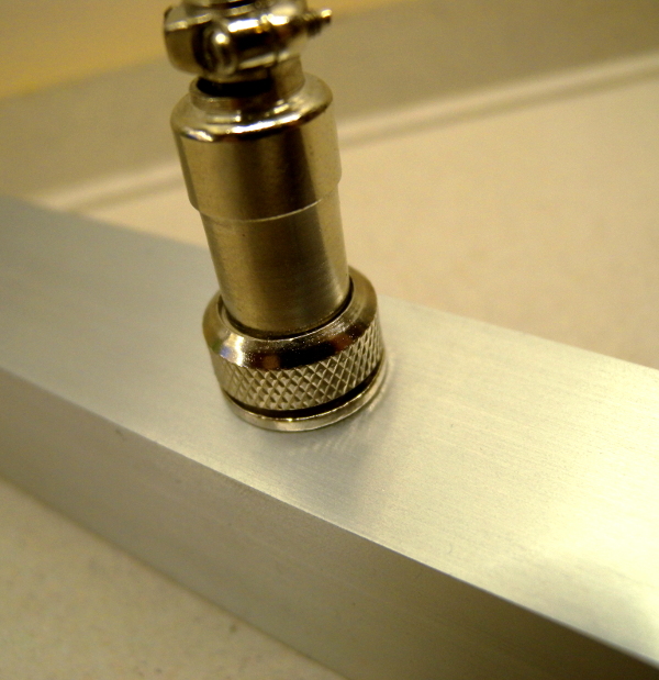 The power/DCF77 connector is quite elegant, I think. Well, OK. It has to be
there, it cannot be optimised away.
The power/DCF77 connector is quite elegant, I think. Well, OK. It has to be
there, it cannot be optimised away.
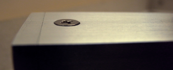 Two stainless steel screws on the back of the casing hold the electronics in place.
They are exactly flush with the aluminium when tightened.
Two stainless steel screws on the back of the casing hold the electronics in place.
They are exactly flush with the aluminium when tightened.
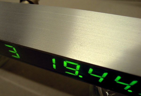 The aluminium casing was brushed with sand paper in various grain sizes.
I built a rig for this to be able to stroke exactly in one direction without
messing up the angle. It took many, many hours to do this. But the result
is stunning, I think. Originally, the piece of aluminium had an
industrial, cheap, raw look. After brushing, it is completely
transformed. To preserve this look, a thin layer of lacquer was applied.
Without it, the aluminium would be very sensitive to finger
prints and to oxidation.
The aluminium casing was brushed with sand paper in various grain sizes.
I built a rig for this to be able to stroke exactly in one direction without
messing up the angle. It took many, many hours to do this. But the result
is stunning, I think. Originally, the piece of aluminium had an
industrial, cheap, raw look. After brushing, it is completely
transformed. To preserve this look, a thin layer of lacquer was applied.
Without it, the aluminium would be very sensitive to finger
prints and to oxidation.
Firmware
I love programming in assembly. So the firmware of this clock is programmed completely in 8-bit AVR assembly code using the GNU AVR assembler under Linux. I wrote my own assembly code libraries for the RTC, for the DCF decoding, and for the MAX chips. Because the previous clock was built with an atmega644, while this uses an attiny864, the signalling was different with the attiny864 lacking some HW support. The assembly libraries had to be extended for this.
I also already mentioned that the time keeping and DCF77 support had to be improved because the clock shows seconds, and should, therefore, properly support leap seconds.
Otherwise, the firmware is quite similar to the previous About-O-Clock, with a good portion of the code shared from libraries for the various hardware modules around the CPU.
The total size of the firmware ROM is around 2500 bytes for this clock.
That's it for now. Let's see what the next clock will be like...
PS
Yes, I switched language for this blog from German to English. The reason is that 90% of the time I read technical and/or tinkering stuff on the Internet, it is in English. For me at least, the German part of the Internet has way less stuff about interesting tinkering projects than the English part. So I feel like I should share my stuff in English, so the people who provided me with interesting stuff now have a chance to read about my stuff in return. Hopefully this will not scare away too many interested German speakers.